syncFURNACE OD Instruction & Installation Manual – Rev 09 Pg. 61 of 81
FLUE GAS VENT & AIR INTAKE SEALING [AT MINIMUM, PERFORM ANNUALLY]:
1. Using Flat-head screw driver, ensure worm-gear clamps are tight that connect the gas-valve air
supply shroud to the combustion air supply tube.
2. Inspect the Combustion Air intake line, both inside the appliance and outside to ensure no leaks or
worn parts are present. Repair any issues that are discovered.
3. Ensure that Stainless Steel Outlet adapter on top of the heat exchanger inside the cabinet is
properly terminated into the heat exchanger flue gas outlet. Ensure that no leaks are present and
it is properly fastened to the top of the cabinet and fully secured in place.
4. Inspect the Flue Gas Vent output line, especially the seal between the venting system and
syncFURNACE. Ensure no leaks or worn parts are present. Repair any issues that are discovered.
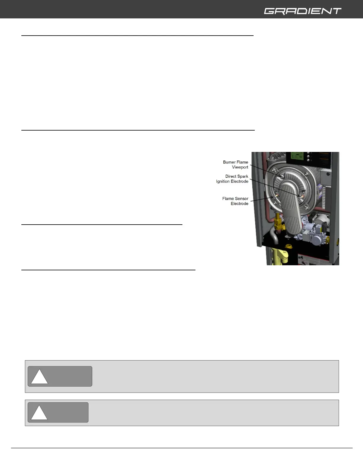
IGNITER & FLAME SENSOR ELECTRODES [AT MINIMUM, PERFORM ANNUALLY]:
1. Using a torx screwdriver remove flame sensor electrode.
2. Using a torx screwdriver remove direct spark ignition electrode.
3. Check both for wear and contamination.
4. Gently clean using a small brush or emery cloth.
5. Check clearance of direct spark ignition electrode.
a. Gap between electrode and ground rod should
= .188” (4.8mm)
6. Re-install back onto burner door.
a. Tighten torx screws to a torque of 2 lb ft (1.36 N*m).
BURNER FLAME [AT MINIMUM, PERFORM ANNUALLY]:
1. With the burner in operation, perform a visual check through
the Burner Flame Viewport (see diagram to right) to ensure
the presence of a stable and uniform burner flame.
ADDITIONAL SERVICE AND MAINTENANCE INSPECTIONS:
1. WATER FLUSH – Flush hard water scale from inside surface of water heater [At Minimum, Perform
Annually]
2. VENTING SYSTEM FOR LEAKS – Inspect venting system and gaskets for leaks, signs of damage
and wear. Replace all worn parts. [At Minimum, Perform Annually]
3. GAS LINE FOR LEAKS [At Minimum, Perform Quarterly]
4. WATER LINES FOR LEAKS [At Minimum, Perform Quarterly]
5. EXTERNAL EXPANSION TANK BLADDER PRESSURE [At Minimum, Perform Annually]
6. FUNCTION OF PRESSURE SAFETY VALVE [At Minimum, Perform Quarterly]
7. FUNCTION OF NO-GAS SAFETY [At Minimum, Perform Annually]