syncFURNACE OD Instruction & Installation Manual – Rev 09 Pg. 57 of 81
TESTING COMBUSTION:
syncFURNACE OD has a pre-mix modulating gas burner combustion system. It uses a negative pressure
gas-valve that is pre-set and calibrated at factory for optimized water heater performance. During a
demand for heat, the syncFURNACE OD controller uses the target supply water temperature for the
demand and modulates burner energy input (between Maximum and Minimum Input Rating) into the
water heater to only provide the required energy so the actual water temperature equals the supply water
temperature target. The negative pressure gas-valve provides fuel on a linear relationship between the
amount of air drawn by the combustion blower. The more air drawn in by the combustion blower, a pre-
set amount of gas is pulled from the gas-valve. The controller speeds up or down the combustion blower
to increase or decrease input rate.
It is recommended that the combustion performance of the burner be verified at the installation site using
a calibrated combustion analyzer.
A measurement needs to be taken at both high & low input levels.
To measure combustion performance:
1. Turn on DHW demand capable of absorbing the load from MAX input (several (3) hot water taps).
2. Enter the SET screen on the CONTROLLER.
a. To enter the SET screen;
i. Push and hold the “SET” button for 10 seconds
ii. Scroll down to “BURNER SETUP” and push “SET”
iii. Push “SET” to get a solid black arrow beside “BURNER ORIDE”
iv. Scroll “BURNER ORIDE” from “OFF” to “MAX”
v. Push “SET” to get a black outline only arrow
vi. Push and hold “SET” for 2 seconds to go back to the “SETUP MENU” screen
vii. Push and hold “SET” for 2 seconds to completely exit the “SETUP MENU”
Note: The controller Burner Override Mode for either MAX or MIN energy input will reset to “OFF”
(default) operating state after a 5 minute period.
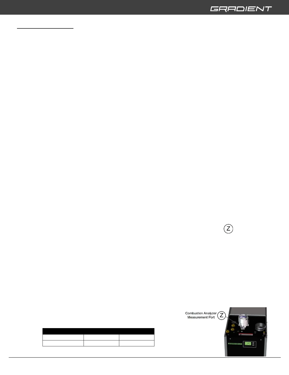
3. Insert combustion analyzer probe into Combustion Analyzer Measurement Port and record
combustion reading.
4. Enter the SET screen on the CONTROLLER and change input to MIN input;
a. To enter the SET screen;
i. Push and hold the “SET” button for 10 seconds
ii. Scroll down to “BURNER SETUP” and push “SET”
iii. Push “SET” to get a solid black arrow beside “BURNER ORIDE”
iv. Scroll “BURNER ORIDE” from “OFF” to “MAX”
v. Push “SET” to get a black outline only arrow
vi. Push and hold “SET” for 2 seconds to go back to the “SETUP MENU” screen
vii. Push and hold “SET” for 2 seconds to completely exit the “SETUP MENU”
5. Insert combustion analyzer probe into Combustion Analyzer Measurement Port and record
combustion reading.
6. Actual combustion CO2% values at MAX and MIN input
must be within 1 % of;
> CONTINUED ON NEXT PAGE