Model G0452/P/Z (Mfg. Since 08/12)
-23-
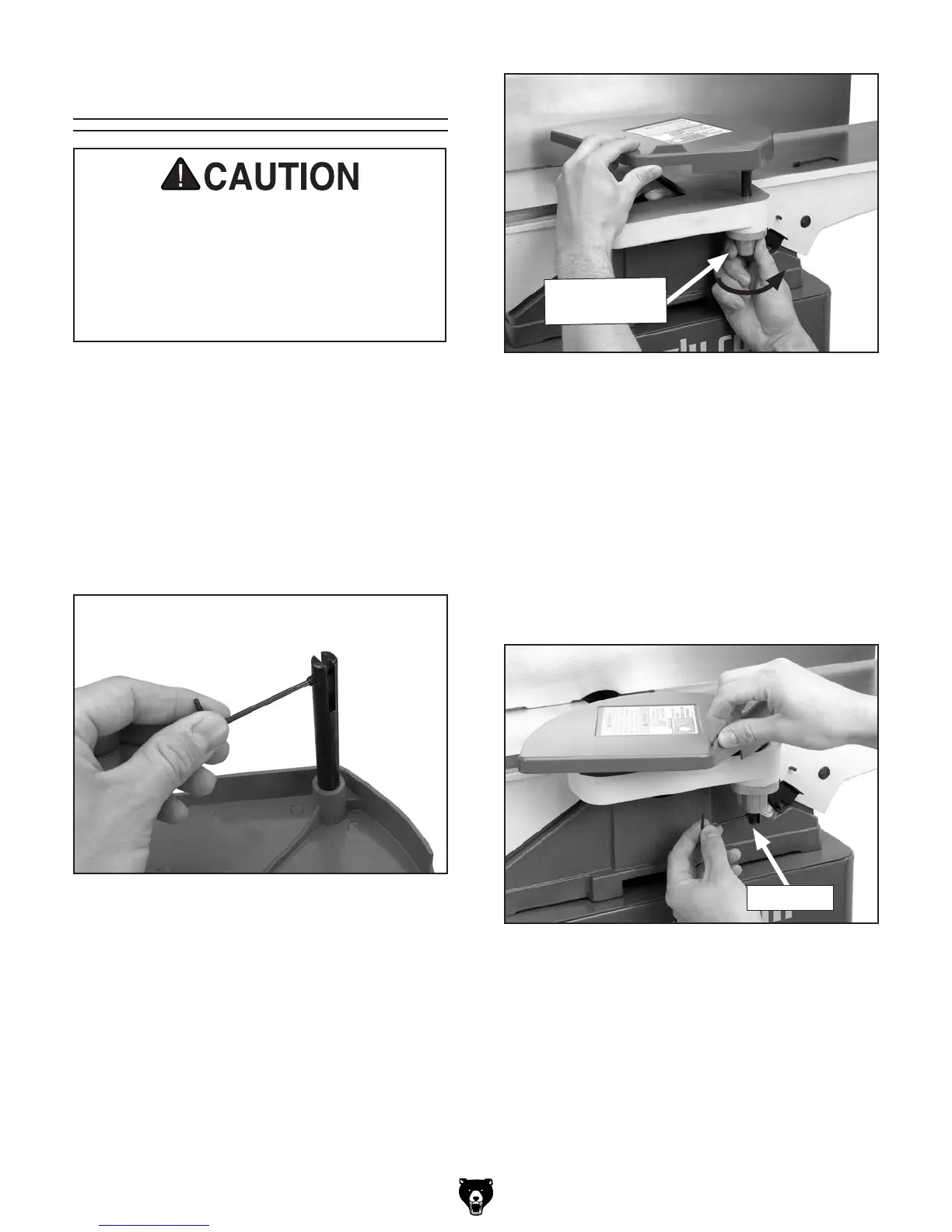
Figure 22. Set screw location.
Components and Hardware Needed: Qty
Cutterhead Guard .............................................. 1
Tools Needed: Qty
Hex Wrench 2.5mm .......................................... 1
To install the cutterhead guard:
1. Remove the set screw in the cutterhead guard
shaft (see Figure 22).
Figure 24. Re-installing set screw.
Set Screw
3. Test the guard by pulling it back and letting
go.
—The guard should snap back over the
cutterhead. If it does, re-insert the set
screw (see Figure 24).
—If the guard is slow to return across the
table, remove the shaft, and add a half turn
to the spring knob and test again. Repeat
this step as necessary.
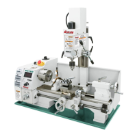
Figure 23. Setting torsion spring knob.
2. Wind the torsion spring knob back counter-
clockwise a half turn, and slide the guard
shaft into the casting shown in Figure 23.
Make sure the slot on the cutterhead guard
shaft fits over the pin that sits inside the
spring knob barrel (hidden from view).
Cutterhead Guard
The cutterhead guard is a critical safety
feature on this machine. A torsion spring is
mounted on the cutterhead guard shaft to
help it return to its proper position over the
cutterhead after a cutting operation. This
torsion spring must have spring pressure
during guard installation to work properly.
Torsion Spring
Knob
 Loading...