Model G0623X/G0623X3 (Mfg. Since 5/12)
-25-
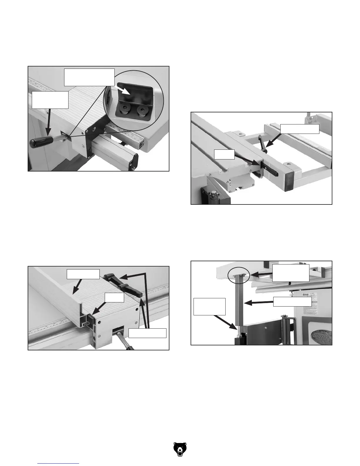
Note: The fence should slide smoothly on the
rail; if it doesn't, remove the fence base and
adjust the spring pressure plate mounting
position on the fence base (see Figure 24).
15. Place a 12mm flat washer on the crosscut
table lock lever, then insert it through the
crosscut fence and thread the M12-1.75
T-nut onto the end approximately two turns.
16. Align the T-nuts on the crosscut table with
the T-slot in the face of the sliding table,
then slide the crosscut table into position on
the sliding table (Figure 26) and tighten the
crosscut table lock lever.
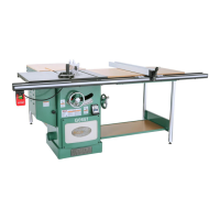
13. Thread the rip fence lever into the fence base
(Figure 24), tighten the hex nut against the
rip fence base to keep the lever in place.
14. Slide the rip fence on the fence base T-bar as
shown in Figure 25. Use the two lock levers
on the opposite side of the fence base to
secure the fence in position.
Figure 26. Crosscut table installation.
T-Slot
Lock Lever
17. Place the crosscut table support leg on the
extension arm, and attach it to the crosscut
table with four M6-1 x 16 cap screws, 6mm
lock washers, and 6mm flat washers.
Figure 27. Support leg installed.
Support Leg
Extension
Arm
Attachment
Location
Figure 24. Location of spring pressure plate for
fence slide adjustments.
Spring Pressure
Plate
Rip Fence
Lever
Figure 25. Rip fence installed on fence base.
T-Bar
Rip Fence
Lock Levers
 Loading...