-42-
Model G4000 (Mfg. Since 8/09)
a
127
b
40
80
40
120
a
120
b
40
80
40
127
Lever
a b
n
1"
mm
0.75
1.25 1.75
1 2 3 4 5 6 7 8 9
60 30 8 9 9.5 10 11
11.5
12 13 14
30 30 16 18 19 20 22 23 24 26 28
30 60 32 36 38 40 44 46 48 52 56
Lever
a
b
7 1 1 4 7 1 1 1 7 1 1
30 28
30
30 30 30 30 42 60 60 60
60 60
60
45 30 36 30 36 30 36 30
0.5 0.7 0.8 1 1.5 2 2.5 3
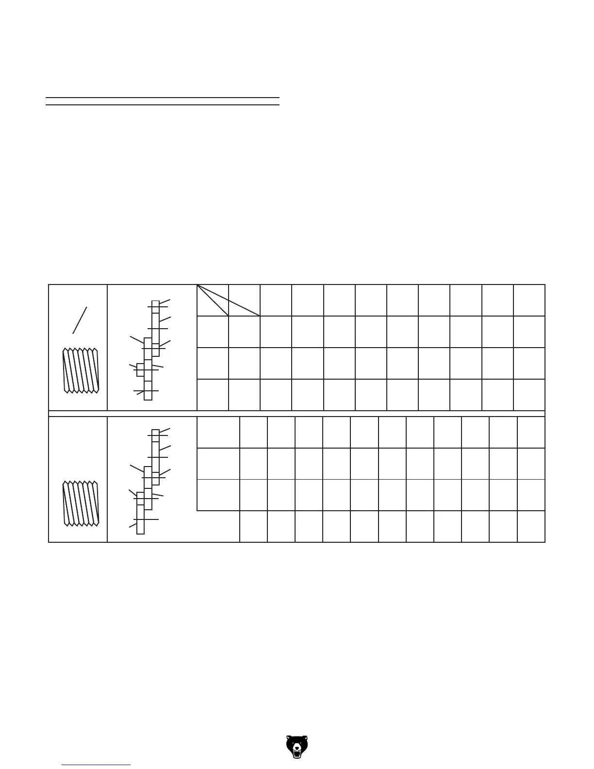
Figure 60. Model G4000 threading charts.
Understanding
Threading Charts
The threading charts illustrated in Figure 60
show the various feed rate lever and change gear
configurations for the inch and metric threading
operations that your lathe can perform.
The top chart is for inch threading. Find the TPI for
your operation in the columns under the top row of
numbers from 1 to 9. This top row is the setting for
the feed rate lever. The correct "a" and "b" gears
to use are shown in the two left columns, and the
configuration of these gears is illustrated to the
left of that.
For example, for a inch thread pitch of 11, the feed
rate lever is set to 5, and the 60T "a" and the 30T
"b" gears are used.
The bottom metric threading chart is arranged
with the thread pitch selection in the bottom row,
the feed rate lever setting in the top row, and the
"a" and "b" change gear selection in the middle
rows.
 Loading...