99
GB
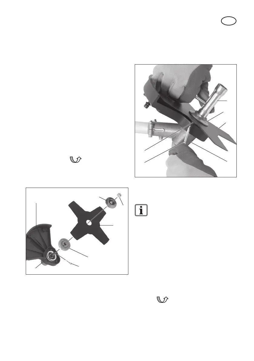
6. Unscrew the xing nut clockwise with
the aid of the maintenance key (26)
and remove the top ange (33b) and
the metal cutting blade (18).
33b
18
26
25
19
pic. 6
33a
Installing/Removing the Reel
Capsule (Picture 7)
Dismantling the metal cutting blade
is described in the section on “In-
stalling/Removing the Metal Cut-
ting Blade”.
Installing the protective cover / thread
reel:
1. Screw the protective cover / reel capsule
(15) onto the protective cover / metal cut-
ting blade (20) using the 3 screws and
nuts (36) enclosed.
Installing the reel capsule:
2. Screw the reel capsule (16) anticlock-
wise onto the cutting head holder
by hand, as indicated in the diagram.
3. Remove the protective cap on the thread
cutter (14).
1. If applicable, unscrew the top (33b)
and bottom (33a) anges mounted on
the cutting head holder (19).
2. Screw the protective cover (15) onto
the cutting head holder (19) using the
3 screws (34) enclosed.
Installing the metal cutting blade
(picture 5b):
3. Place the metal cutting blade (18) and
anges (33a+b) on the cutting head
holder (19) in the following order:
Bottom ange (33a) – metal cutting
blade (18) – top ange (33b).
4. Screw on the metal cutting blade (18)
anticlockwise using the xing nut
(35) and with the aid of the maintenance
key (see picture 2, no. 26).
Insert the splint (23).
33b
33a
23
35
18
19
15
pic. 5b
Removing the metal cutting blade
(picture 6):
5. To lock the axle, push the enclosed
metal pin (25) sideways into the hole
provided on the cutting head holder
(19) and on the bottom ange (33a).
 Loading...