English (GB)
68
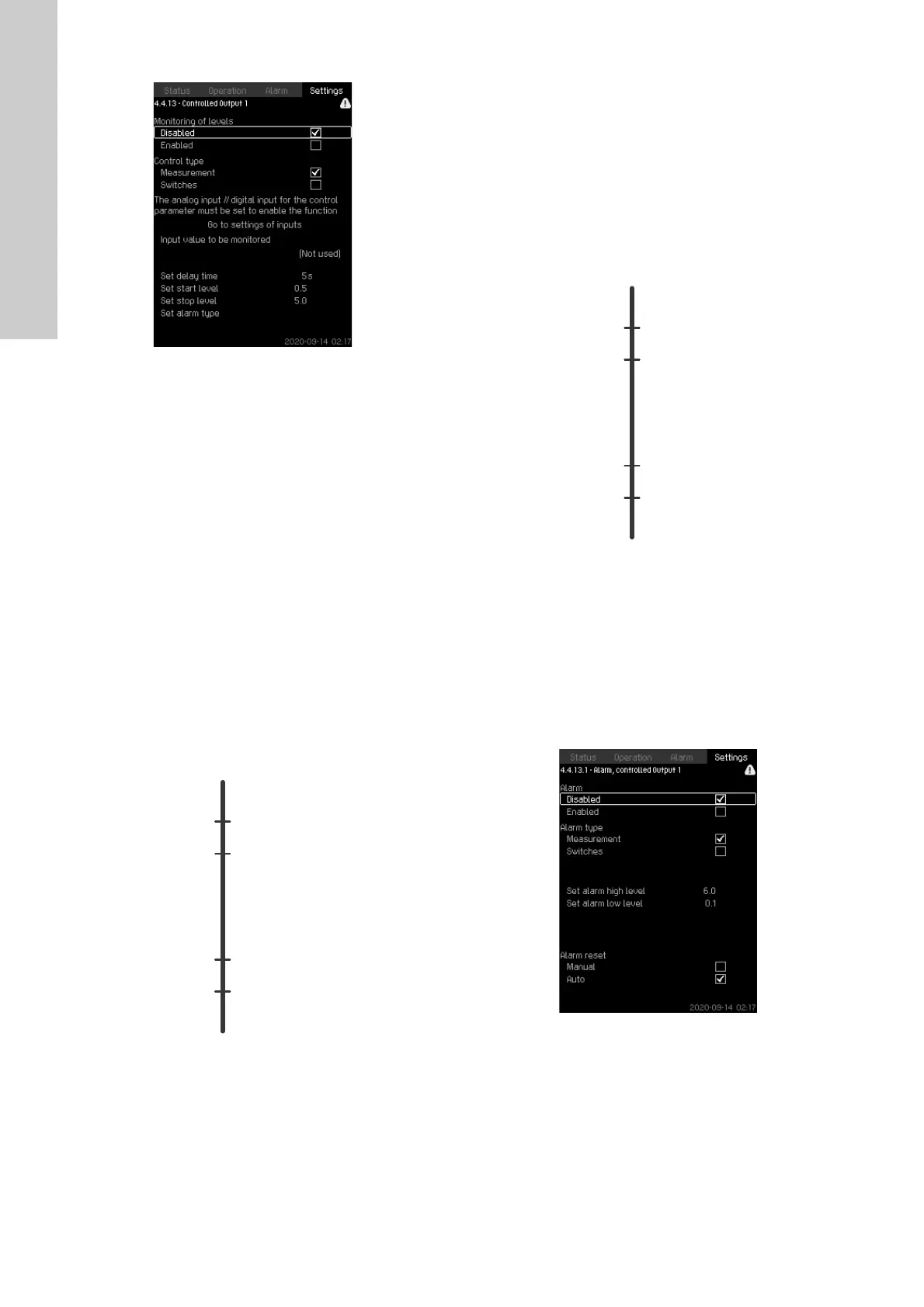
8.7.70 Controlled output 1-2(4.4.13-4.4.14)
Fig. 122 Controlled output 1-2
Description
With this function, CU 352 can monitor up to four different limits
by a set of indicators (switches and/or analog values) and can
activate a digital output. These four limits are Start, Stop, High
and Low. The reaction of the digital output depends on the
monitoring type, which can be Normal or Inverse. Inverse means
that the function of the indicators (switches and/or analog values)
works opposite to their function in Normal. For example, when
Normal uses the "Tank filling" application, Inverse uses the "Tank
emptying" application.
Normal controlled output:
1. Low: If the level drops below the Low limit, a warning occurs
and activates the digital output "Controlled output, Low" and
simultaneously activates the digital output "Controlled output",
if it is not activated beforehand.
2. Start: If the level drops below the Start limit, the digital output
"Controlled output" is activated.
3. Stop: If the level exceeds the Stop limit, the digital output
"Controlled output" is deactivated.
4. High: If the level exceeds the High limit, a warning occurs and
activates the digital output "Controlled output, High" and
simultaneously deactivates the digital output "Controlled
output", if it is not deactivated beforehand.
Fig. 123 Controlled output
Inverse controlled output:
1. Low: If the level drops below the Low limit, a warning occurs
and activates the digital output "Controlled output, Low" and
simultaneously deactivates the digital output "Controlled
output", if it is not deactivated beforehand.
2. Stop: If the level drops below the Stop limit, the digital output
"Controlled output" is deactivated.
3. Start: If the level exceeds the Start limit, the digital output
"Controlled output" is activated.
4. High: If the level exceeds the High limit, a warning occurs and
activates the digital output "Controlled output" and
simultaneously activates the digital output "Controlled output,
High", if it is not activated beforehand.
Fig. 124 Inverse controlled output
Setting range
1. Alarm type: select measurement or switches.
2. Set delay time: A delay can be set between the detection of
an exceeded indicator and the activation of the digital output.
3. Set start level: set the start level for activating the output
(hidden if Switches is selected).
4. Set stop level: set the stop level for deactivating the output
(hidden if Switches is selected).
5. Set Alarm type: configure the alarm.
Fig. 125 Alarm measurement

 Loading...
