5
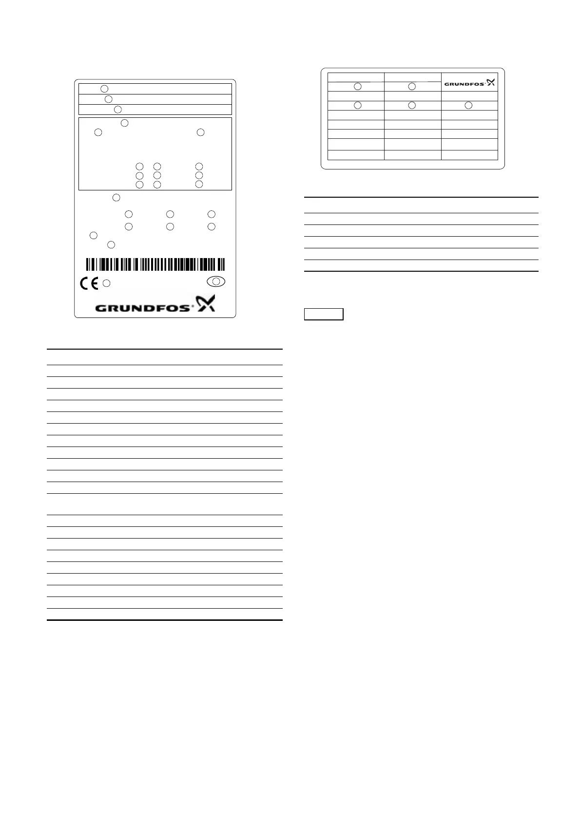
5. Nameplate
The nameplate of the Control MPC is fitted on the base frame.
See position 2 in fig. 2.
Fig. 2 Nameplate
6. Software label
The software label is placed on the back of the CU 351 controller.
Fig. 3 Software label
* Applies only to booster systems.
** Applies only to CR, CRI, CRE and CRIE pumps.
TM03 9956 4707
Pos. Description
1 Type designation
2 Model
3 Serial number
4 Supply voltage
5 Nominal current [A]
6 Maximum ambient temperature in °C
7 Number of mains-operated pumps
8 Motor power in kW for mains-operated pumps
9 Nominal voltage in volts for mains-operated pumps
10 Number of pumps with frequency converter
11 Motor power in kW for pumps with frequency converter
12
Nominal voltage in volts for pumps with frequency
converter
13 Number of pilot pumps
14 Motor power in kW for pilot pump
15 Nominal voltage in volts for pilot pump
16 Order number
17-22 Options
23 Enclosure class
24 Weight [kg]
25 CE-mark
26 Country of origin
Type:
Model:
Serial No.:
Order No.:
Options:
IP
Weight: kg
Made in
96778609
1
2
3
4
78 9
16
17
23
24
26
25
Mains supply:
I
n
: A T
AMB.
:
o
C
PU
n
No. kW V
Fixed speed pumps:
E-pumps:
Pilot Pump:
10
11 12
18
20 21
19
22
13 14
15
5
6
TM03 1742 3105
Pos. Description
1 Control MPC - GSC file number
2 Control MPC options - GSC file numbers
3 Hydro MPC - GSC file number*
4 Hydro MPC options - GSC file numbers*
5 Pump data - GSC file numbers**
A GSC (Grundfos Standard Configuration) file is a
configuration data file.
1. Control MPC 3. Hydro MPC
5. Pump data
96586126
4. H-MPC options2. C-MPC options
CONFIGURATION STEPS - PLEASE FOLLOW THE NUMBERS
1
2
3
4 5