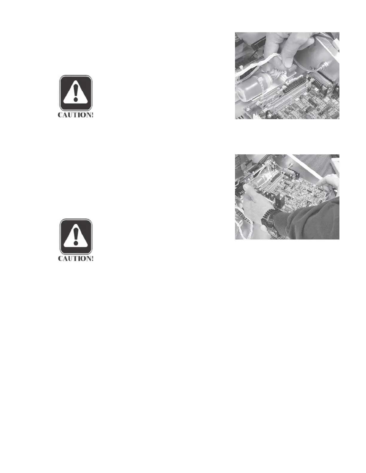
Disassembly
Step 6
Remove the printer power cable by
pulling the cable connector straight
up.
CAUTION
It is not necessary to disconnect the
probe from the analog board to re-
move the analog board.
Step 7
Remove the four retaining screws at the corners of the board.
Step 8
Remove the analog board by grasp-
ing the upper left and lower right cor-
ners and pulling the board straight
away from the probe connector.
Gen-
tly rock the board back and forth
slightly to disengage the board from
the probe connector.
CAUTION
Handle the board carefully by
touching only the edges. Do not
bend circuit board components.
GSI TympStar Version 1 and Version 2 Service Manual 5 - 5
 Loading...