25
1. Wear an ESD wrist strap. Make sure the strap makes good skin contact and is reliably
grounded.
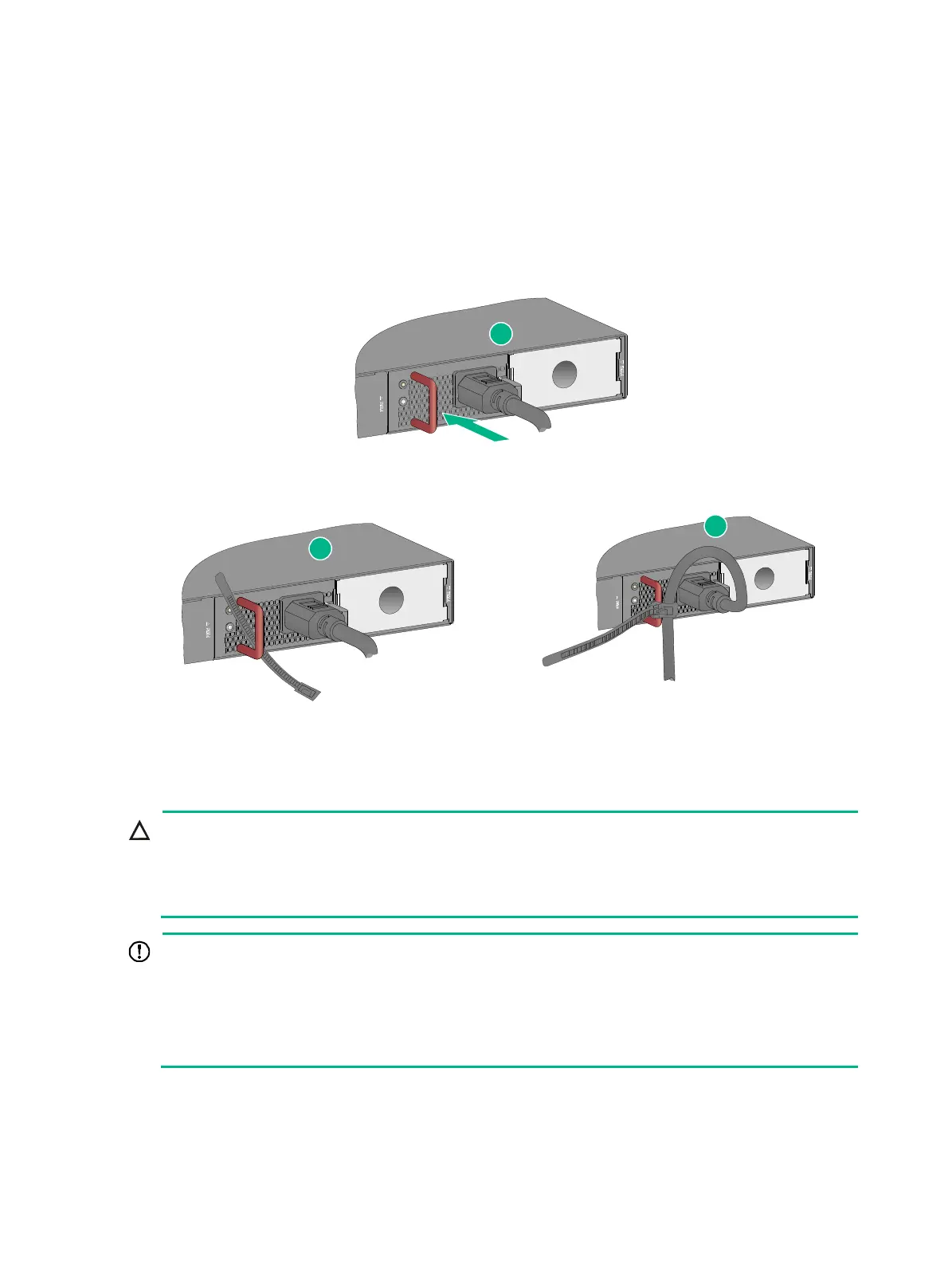
2. Plug the female connector of the power cord into the power receptacle on the power module, as
shown by callout 1 in Figure 34.
3. Use a ca
ble tie to secure the power cord to the handle of the power module, as shown by callout
2 and callout 3 in Figure 34.
4. Con
nect the other end of the power cord to an AC power source.
Figure 34 Connecting the power cord for a PSR720-56A power module
Installing and removing an expansion card
CAUTION:
• Do not touch the surface-mounted components on an expansion card directly with your hands.
• Do not use excessive force when you install or remove an expansion card.
• Do not install or remove an expansion card while the switch is starting up.
IMPORTANT:
• An S6520X-18C-SI switch must use PSR150-A1 or PSR150-D1 power modules for power
supply when it is installed with an LSPM6FWD firewall module.
• An S6520X-26C-SI switch must use PSR150-A1 or PSR150-D1 power modules for power
supply when it is installed with an LSWM2SP8P, LSWM4SP8PM, LSWM2MGT8P or
LSWM2XMGT8P interface card, or an LSPM6FWD firewall module.
The S6520X-18C-SI, S6520X-26C-SI, S6520X-26MC-SI, S6520X-26MC-UPWR-SI,
S6520X-26XC-UPWR-SI, and S6520X-54XC-UPWR-SI switches each provide an expansion slot on
the rear panel. For the expansion cards available for the switches, see "Expansion cards."
1
2
3
 Loading...


