50
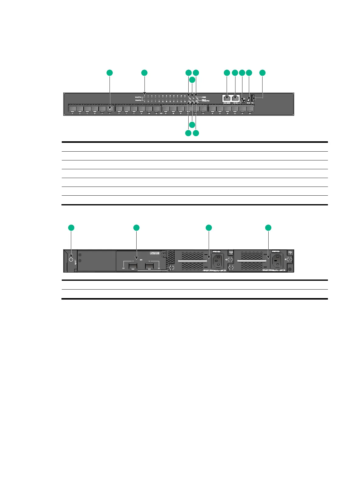
S6520X-26C-SI
Figure 60 Front panel
(1) SFP+ port (2) SFP+ port LED
(3) Power module 1 status LED (PWR1) (4) System status LED (SYS)
(5) Management Ethernet port LED (LINK/ACT) (6) Management Ethernet port
(7) Console port (CONSOLE) (8) Micro USB console port
(9) Mode button (10) USB port
(11) Mode LED (MODE) (12) Expansion card status LED (SLOT)
(13) Power module 2 status LED (PWR2)
Figure 61 Rear panel
(1) Grounding screw (2) Expansion card
(3) Power module 1 (PWR1) (4) Power module 2 (PWR2)
An S6520X-26C-SI switch comes with power module slot 1 empty and power module slot 2 installed
with a filler panel. You can install one or two power modules for the switch as required. In Figure 61,
two PSR7
5-12A AC power modules are installed in the power module slots. For more information
about installing and removing a power module, see "Installing and removing a power module."
An S6520X
-26C-SI switch comes with a filler panel in the expansion slot. You can select an
expansion card for the switch as required. In Figure 61, an LSWM2
SP2PM interface card is installed
in the expansion slot. For more information about installing and removing an expansion card, see
"Installing and removing an expansion card."
1 2 3
4
6 7 85 9
11
12
13
10
1 2 3 4
 Loading...


