46
Appendix A Chassis views and technical
specifications
Chassis views
S6520X-16ST-SI
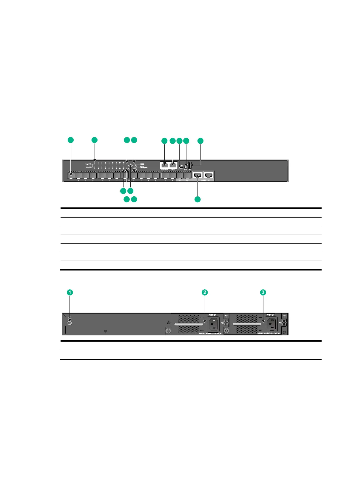
Figure 50 Front panel
(1) SFP+ port (2) SFP+ port LED
(3) Power module 1 status LED (PWR1) (4) Management Ethernet port LED (LINK/ACT)
(5) Management Ethernet port (6) Console port (CONSOLE)
(7) Micro USB console port (8) Mode button
(9) USB port (10) 1/10GBASE-T autosensing Ethernet port
(11) Mode LED (MODE) (12) System status LED (SYS)
(13) Power module 2 status LED (PWR2) (14) 1/10GBASE-T autosensing Ethernet port LED
Figure 51 Rear panel
(1) Grounding screw (2) Power module 1 (PWR1)
(3) Power module 2 (PWR2)
An S6520X-16ST-SI switch comes with power module slot 1 empty and power module slot 2
installed with a filler panel. You can install one or two power modules for the switch as required.
In Figure 51, two PSR75
-12A AC power modules are installed in the power module slots. For more
information about installing and removing a power module, see "Installing and removing a power
module."
1
11
2 3 4
5 6 7 8
10
14
13
12
9
 Loading...


