54
in the expansion slot. For more information about installing and removing an expansion card, see
"Installing and removing an expansion card."
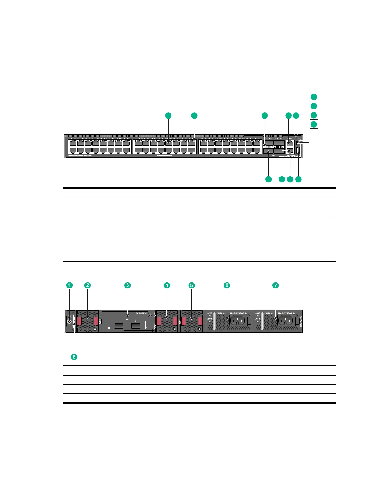
S6520X-54XC-UPWR-SI
Figure 68 Front panel
(1) 10G/5G/2.5G/1000/100BASE-T autosensing Ethernet port
(2) 10G/5G/2.5G/1000/100BASE-T autosensing Ethernet port LED
(3) QSFP+ port LED (4) Console port (CONSOLE)
(5) Mode button (6) System status LED (SYS)
(7) Expansion card status LED (SLOT) (8) Mode LED (MODE)
(9) Micro USB console port (10) USB port
(11) Management Ethernet port LED (LINK/ACT) (12) Management Ethernet port
(13) QSFP+ port
Figure 69 Rear panel
(1) Grounding screw (2) Fan tray 1 (FAN1)
(3) Expansion card (4) Fan tray 2 (FAN2)
(5) Fan tray 3 (FAN3) (6) Power module 1 (PWR1)
(7) Power module 2 (PWR2) (8) Serial label pull tab
The ESN serial number and MAC address of the S6520X-54XC-UPWR-SI switch can be found on
the serial label pull tab.
An S6520X-54XC-UPWR-SI switch comes with power module slot 1 empty and power module slot 2
installed with a filler panel. You can install one or two power modules for the switch as required.
In Figure 69, two PSR720
-56A AC power modules are installed in the power module slots. For more
9
1 3
6
7
2 4
8
5
12
11 10
13
 Loading...


