!
"
$
#
/
%
&
(
)
BL
BM
BN
Planer-Thicknesser
A3-26 / A3-31 / A3-41
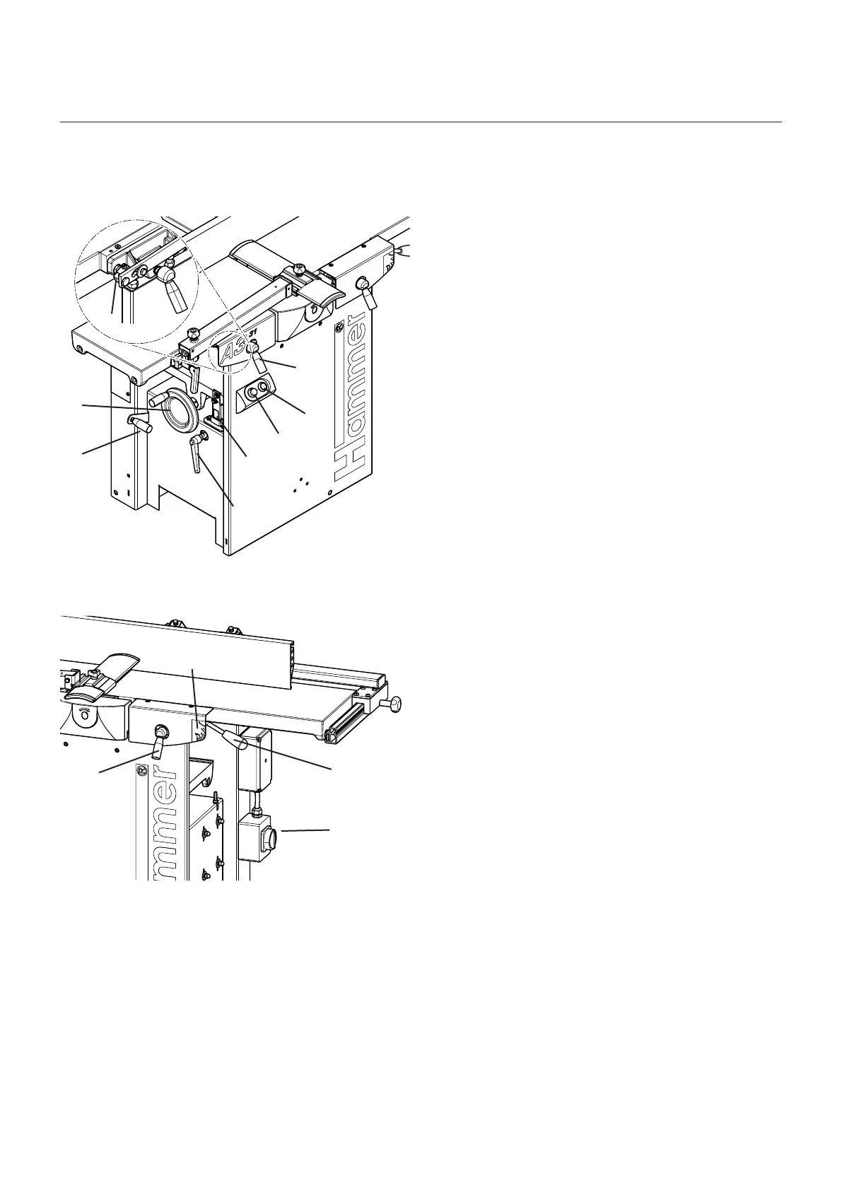
5.5 Operation and display elements
! Gear lever
• Position O: (pull out)
Surface planing, Jointing, Bevelling/Tapering,
mortising and idle machine for a longer period of
time
• Position I: Thickness planing
" System handwheel
Adjusting the height on the thicknessing unit (Thick-
ness planing height)
# Eccentric (Surface planing)
Adjusting the height of the receiver side of the planer
table
$ Single-hand clamping lever
Clamping the outfeed-side of the planer table
% Green push button
Switching on the machine
& Red push button
Emergency stop and switching off the machine
/ Scale (Thickness planing)
Specifying the thicknessing height
( Single-hand clamping lever
Clamping the planer table
) Scale (Surface planing)
Specifying the chip thickness on the feeder-side of
the planer table
BL Single-hand clamping lever
Clamping the infeed-side of the planer table
BM Adjustment handle (Surface planing)
Adjusting the height of the feeder-side of the planer
table
BN Main switch (if available)
• Position 0: Mains voltage off
• Position I: Mains voltage on
Fig. 5-15: Operation and display elements
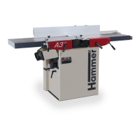
Fig. 5-16: Operation and display elements
Assembly