!
"
#
Planer-Thicknesser
A3-26 / A3-31 / A3-41
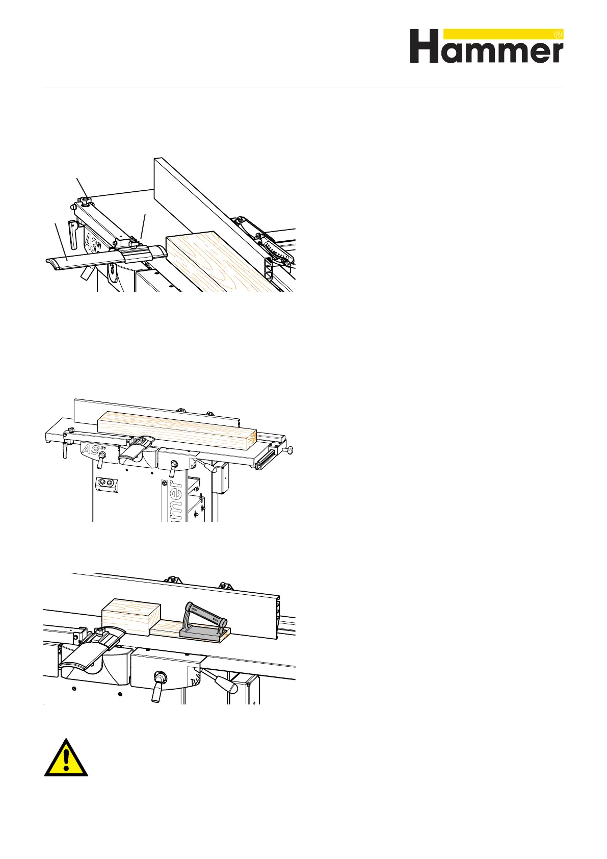
Fig. 9-7: Bridge guard
1. Before beginning any maintenance work on the
machine, switch it off and secure it against acciden-
tally being switched on again.
2. Both planer tables must be shut and fixed with the
clamping levers.
3. Set the gear lever to the “0” setting.
4. Extraction system must be connected
5. Planer fence: set at 90°.
6. Adjusting the depth of cut.
7. Adjust the joint, if necessary.
8. Adjust the bridge guard
• Loosen the clamping screw.
• Pull out the guard rail (slightly more than the workpie-
ce width).
• Place the workpiece against the planer fence and
push it to the front edge of the feeder planer table
(not over the cutterblock!).
• Bring the guard rail right up to the workpiece
• Tighten the clamping screw.
• Use the setscrew to lower the guard rail to the planer
table.
9. Switch the machine on
10. Take up work position.
11. Machining the workpiece:
• Lay your hands flat on the workpiece, ensuring that
your fingers are balled into a fist and thumbs are
pressed against the workpiece.
• Guide the workpiece straight along the fence over
the feeder-side of the planer table.
• As soon as it is possible, use both hands to
continuously push the workpiece on the receiver-side
of the planer table.
• The pushing stick should not be thicker than the work-
piece.
12. If you are not going to continue working, switch off
the machine and secure it against being turned on
again accidentally
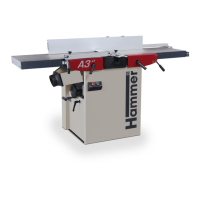
9.4.5 Surface planing - Workpieces over 75 mm thick
!Setscrew
"Clamping screw
#Protective rail
Fig. 9-9: Wooden push stick and push block
Attention! Risk of injury!
When planing smaller workpieces, use a pushing stick or pushing block.
Fig. 9-8: Guiding the workpiece
Operation