!
"
#
!
"
Planer-Thicknesser
A3-26 / A3-31 / A3-41
1. Prior to starting to work with the machine, switch it off
and secure it against being switched on again.
2. If necessary, mount the coupler unit (accessory). If
necessary, mount the 2-jaw drilling chuck (accessory).
(See assembly instructions „Drilling chuck and coupler
unit“)
3. Both planer tables must be tilted up and secured with
the fall locks
(Position „Thickness planing“)
4. Affix the drilling table:
• Depth adjustment in the hindmost position and
• Adjust the length in the middle position
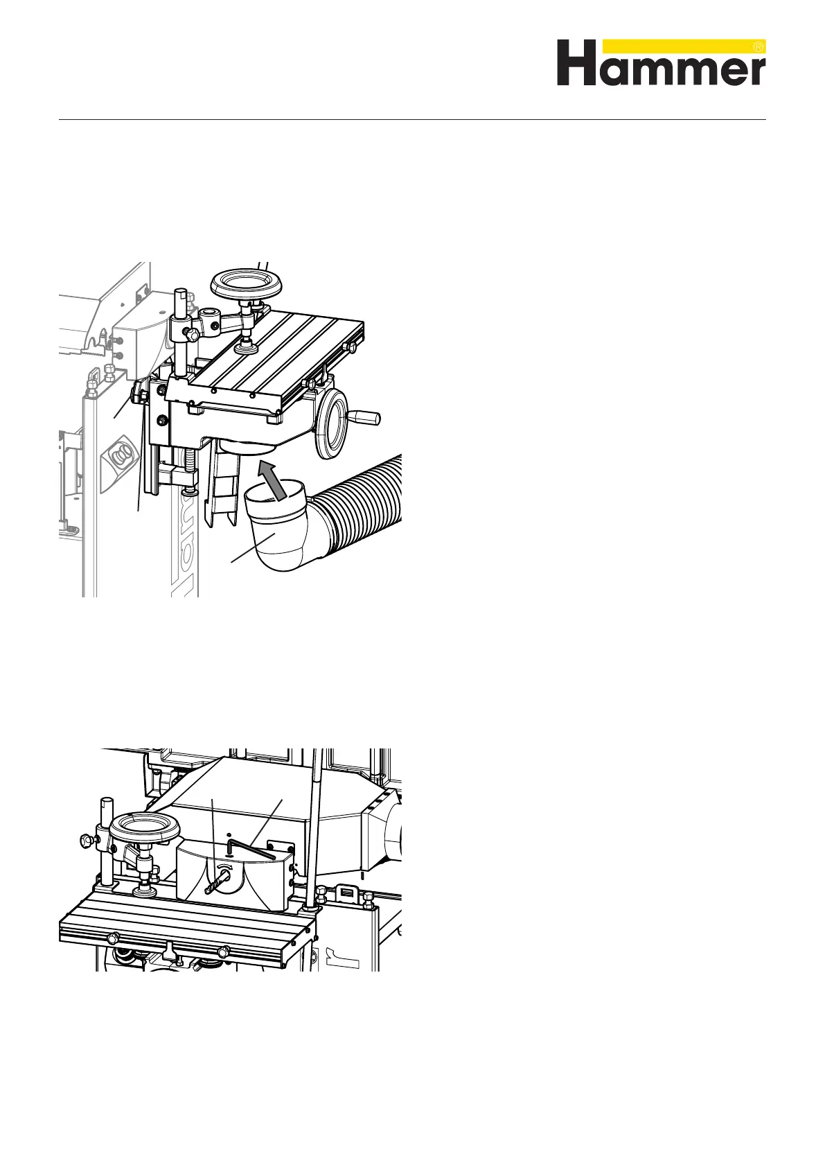
5. Hook the mortising table into the seating bolt
6. Attach the drilling support with the nuts.
7. Connect the drilling support by means of the extractor
port to a suitable extraction system
See Chapter >7.3 Chip extraction<
! Seating bolt
" Nuts
# Vacuum connector
8.9 Retooling to the drilling unit
Fig. 8-13: Mounting the mortising support
8.9.1 Mounting the mortising support
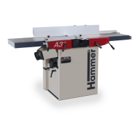
8.9.2 Clamp the drilling tool
1. Prior to starting to work with the machine, switch it off
and secure it against being switched on again.
2. Open the 2-jaw chuck with an 8 mm Allen key.
3. Clamp the authorised drilling tool along the entire
length of the chuck
See Chapter >9.6 Drilling<
4. Clamp the 2-jaw chuck with an 8 mm Allen key (mini-
mum torque 20 Nm).
! Allen key 8 mm
" Drilling tool
Fig. 8-14: Clamp the drilling tool
Making adjustments and preparations