!
"
"
!
!
Planer-Thicknesser
A3-26 / A3-31 / A3-41
5.2 Accessories
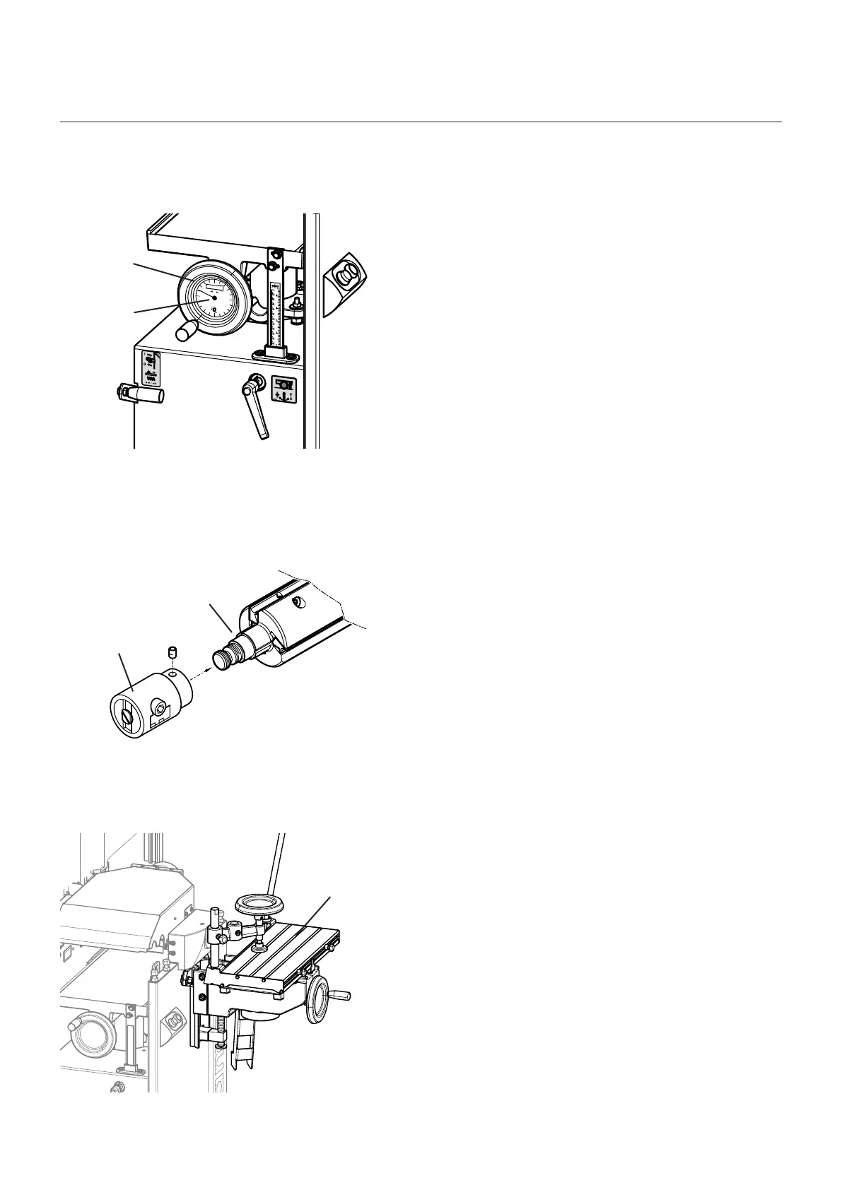
System handwheel
Art. No. 12.1.311
Digital clock
Art. No. 01.1.202 (Display in “mm”)
Art. No. 01.2.202 (Display in “inch”)
The digital display is built into both the thicknessing
height adjustment system handwheel and the drilling
height adjustment system handwheel (drilling support is
an add-on option).
Exact adjustments to one tenth of a millimeter are possib-
le with the digital display
(See assembly instructions „Digital clock“)
! Digital clock
" System handwheel
Fig. 5-2: Digital clock
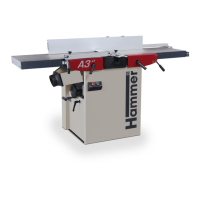
2-jaw drilling chuck
Art. No. 500-118
The drilling chuck is mounted onto the cutterblock. The
mortising chuck holds the mortising tools
(See assembly instructions „Drilling chuck and coupler
unit“)
! 2-jaw drilling chuck
" Cutterblock
Fig. 5-3: 2-jaw drilling chuck
Mortising table / Coupler unit
Art. No. 501-117
The coupler unit is mounted onto the machine frame.
Hang the mortising support into the coupling device and
secure it
(See assembly instructions „Drilling chuck and coupler
unit“ and „Mortising table“)
! Mortising table
Fig. 5-4: Drilling chuck and coupler unit
Assembly