!
!
"
#
$
!"$
#
Planer-Thicknesser
A3-26 / A3-31 / A3-41
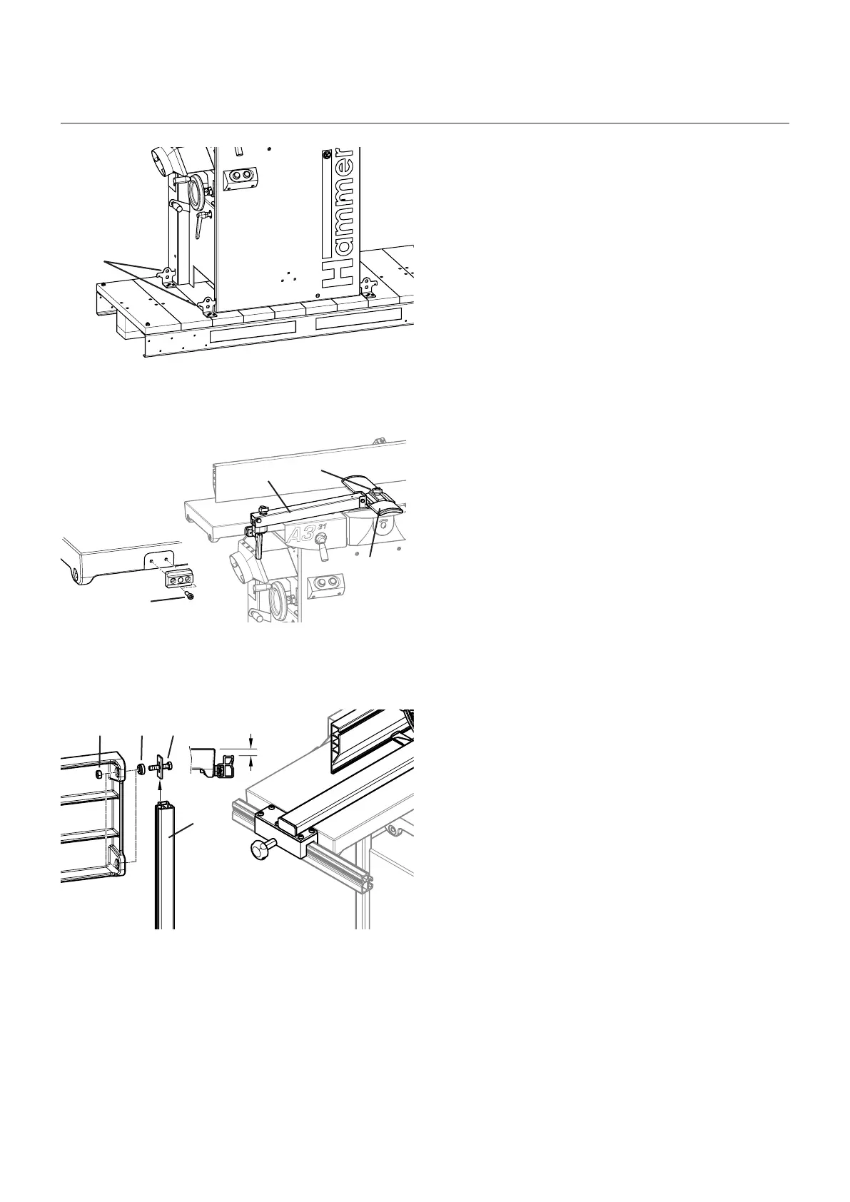
1. The machine will be transported to the installation
location according to the specifications stated in the
„Transport“ chapter and in the enclosed transport and
assembly instructions
2. If necessary, the machine can be bolted down to the
floor with the transport brackets.
! Transport brackets
3. Remove the oxidation protective layer from all blank
machine parts.
4. Assemble the guard rail and bridge guard:
- Bridge guard arm: fasten with allen screws on the
planer table.
- Loosen the clamping screw.
- Protective rail: thread into the arm of the bridge
guard
- Tighten the clamping screw.
! Bridge guard arm
" Allen screws
# Protective rail
$ Clamping screw
Fig. 7-2: Floor mounting
Fig. 7-3: Bridge guard
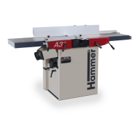
Fig. 7-4: Mount the planer fence
5. Mount the planer fence
• Fasten guide rail to the machine table with screws,
turn locks and spacing washers
• Adjust the distance: 17 mm
(This setting has to be exact.)
• Tighten the nuts.
! Screws
" Spacer washers
# Track
$ Nuts
Setup and installation