AIR CONNECTION
The air filter/regulator and coalescing filter are located at the right end of the power case platform.
Factory air to the machine goes through the filter/regulator to control the air supply for the machine. A
heavy-duty air dryer may have to be added in the air line if the air supply has excessive moisture.
The air volume requirement for a standard machine is 5 to 7 scfm [142 to 200 lm]. Machines that
have the air blast option require much more air flow. The incoming air line should have a minimum in
-
side diameter of 3/8 inch [9.5 mm]. A larger diameter hose may be needed if the air line is especially
long.
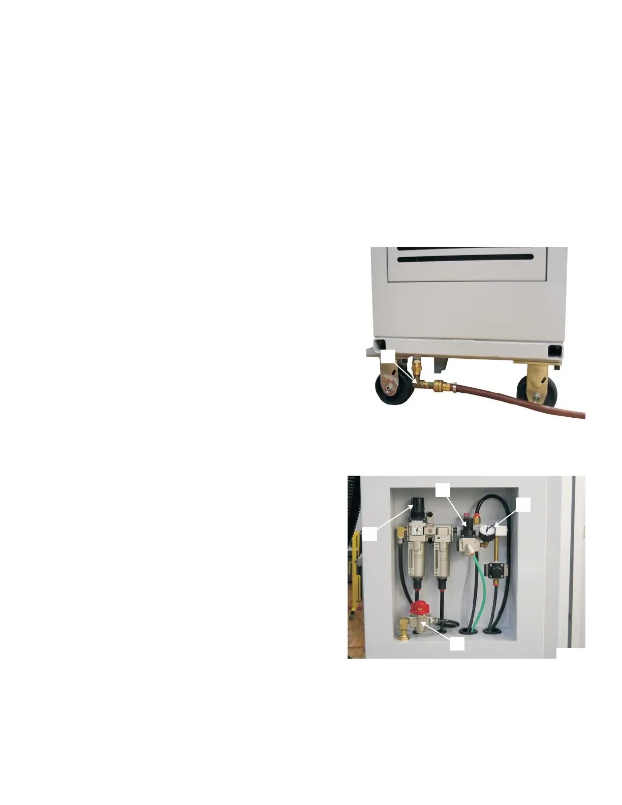
CONNECTING THE AIR SUPPLY
Connect the air supply to nipple "R", Figure 1.29, located on the bottom of the power case platform.
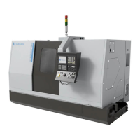
SETTING THE MACHINE AIR PRESSURE
- NOTE -
Do not turn the air supply ON. The
Hardinge technician will check the in
-
coming air line connection.
Once the air line connection has been checked:
1. Turn main air valve "V", Figure 1.30, ON.
2. Pull regulator knob “S” up and set the machine
air pressure at a constant pressure from 70 psi
to 90 psi [4.9 to 6.2 bar]. Press the knob down
when adjustment is complete.
3. Check turret air pressure gauge "U". Pressure
should be between 18 to 22 psi [1.3 to 1.5 bar].
4. If necessary, pull regulator knob “T” up and set
the turret air pressure as specified in the
previous step. Press the knob down when
adjustment is complete.
The machine main air pressure switch is preset at
60 psi [4.2 bars]. If the machine air pressure is below
this setting, an alarm message appears on the con
-
trol display screen and the control is forced into
Emergency Stop.
Refer to the maintenance manual (M-506) for
additional information about the air system.
M-507C 1-19
Figure 1.29 - Air Supply Connection
R
TP7865A
Figure 1.30 - Air Control Assembly
TP7857B
U
T
S
V