FOOT SWITCH INSTALLATION
- NOTE -
Depending on configuration, the machine will be equipped with one or two foot
switches.
The foot switches, shown in Figure 1.64, are used for the following functions:
•
Manual main spindle collet closer operation
•
Manual tailstock operation
•
Manual sub-spindle collet closer operation
The foot switches are not interchangeable. Each foot switch is labeled and wired for a specific func
-
tion.
Refer to the operator's manual (M-505) for information on foot switch operation.
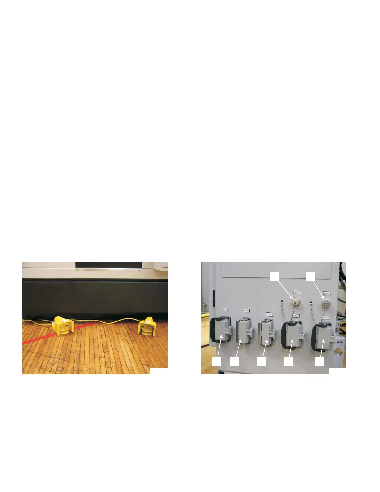
Connect the foot switch plug to the appropriate receptacle on the side of the power case.
Receptacle "R" [5701PL], Figure 1.65, is for the main spindle Collet Open/Close foot
switch.
Depending on machine configuration, receptacle "S" [5705PL] is for:
Tailstock foot switch
-or-
Sub-spindle Collet Open/Close foot switch
1-40 M-507C
Figure 1.64 - Foot Switches
in Front of Machine
TP7996
Figure 1.65 - Receptacles
on Side of Power Case
TP7960A
R S
T U V W X