10. Close and secure the control box door.
11. Turn chiller unit power switch "E", Figure 1.51, to the ON position
12. Cut the cable ties to release coolant hoses "B", Figure 1.49, from the chiller unit.
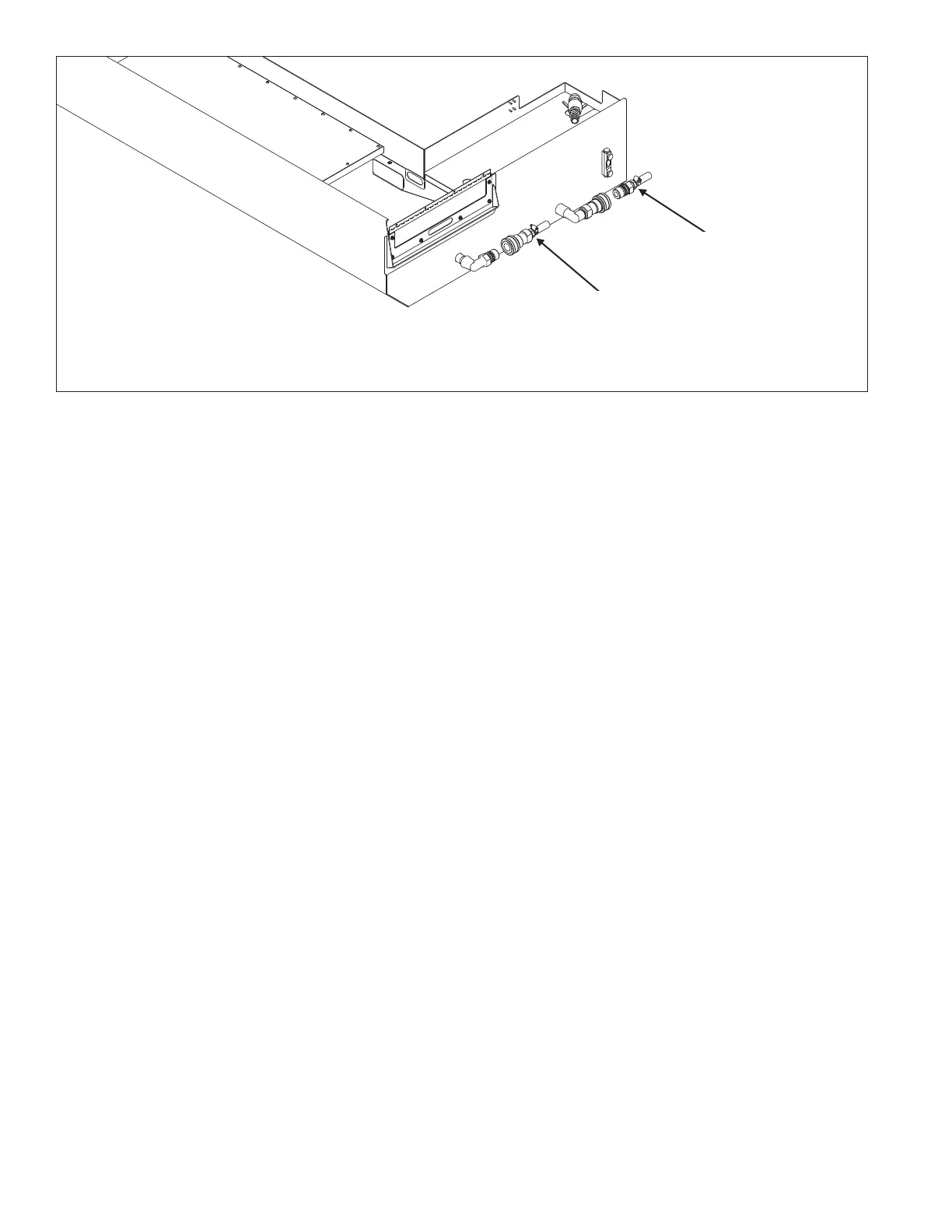
13. Connect the hoses to the coolant tank. Refer to Figure 1.53.
1-30 M-507C
Figure 1.53 - Coolant Chiller Hose Connections on the Coolant Tank
TI5796
Hose connected to coolant
chiller DISCHARGE port
Hose connected to coolant
chiller RETURN port