Chapter 2 Installing the ProStream 9100
© 2016 Harmonic Inc. All rights reserved. 36 ProStream 9100 Release 17.5, Rev A
The Boot Sequence
5. Strip up to 0.3 inches (8 mm) of insulation from each of the wires coming from the DC power
source.
Do not strip more than this length f
rom each wire. Stripping more leaves uninsulated wire
exposed outside the DC connector after the assembly is complete.
6. Insert a small screwdriver into the rectangular ho
le directly above the hole in the DC
connector where you want to insert the first cable and press down on the screwdriver.
This opens the cage clamp for this section of the DC plug connector.
NOTE: WAGO also sells tools specifically designed to open cage clamps easily. For more information,
either visit the WAGO web site at www.wago.com, or call WAGO at 1-800-346-7245 and request
information about items 210-250 or 231-131.
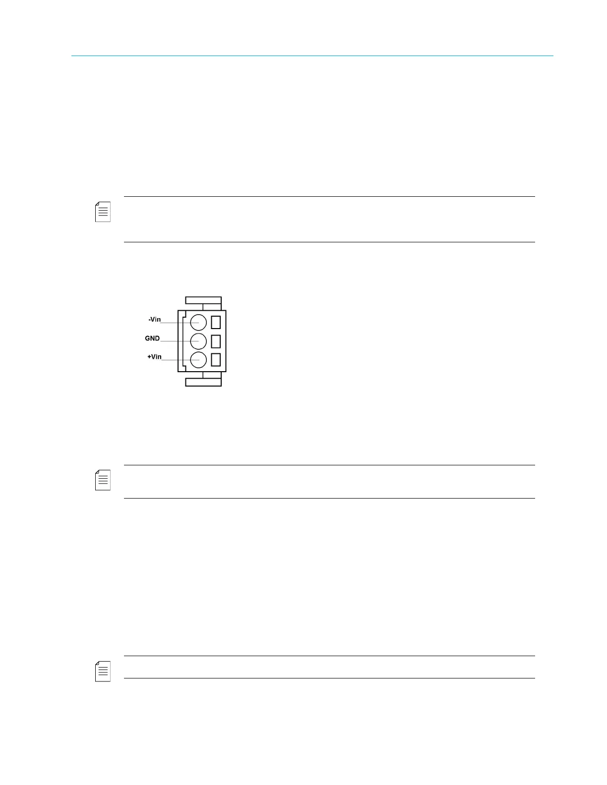
7. Feed the exposed section of the wire into the matching hole in the DC plug connector, as
shown in Figure 2–8
Figure 2–8: DC Power Connector Detail
8. Repeat step 5 thr
ough step 7 for the other two wires to complete the assembly of the DC
input cable.
NOTE: If you need to remove a wire from the DC plug connector, insert a small screwdriver into the slot
directly above the wire and press down on the screwdriver to free the wire from the cage clamp.
The Boot Sequence
The boot sequence begins as soon as you plug in your device. This section describes the boot
sequence, including the messages that appear on the local control panel display.
Local Control Panel Display Messages during Bootup
Messages on the local control panel indicate progress during boot-up. During a successful boot,
many events occur so quickly you cannot see the messages. The following sections describe the
messages that you can see during boot attempts.
NOTE: During the boot sequence, do not press any key on the keypad.
The following sequence describes the display on the vacuum fluorescent display (VFD) during a
successful startup: