23
Accessory connection 18, 19
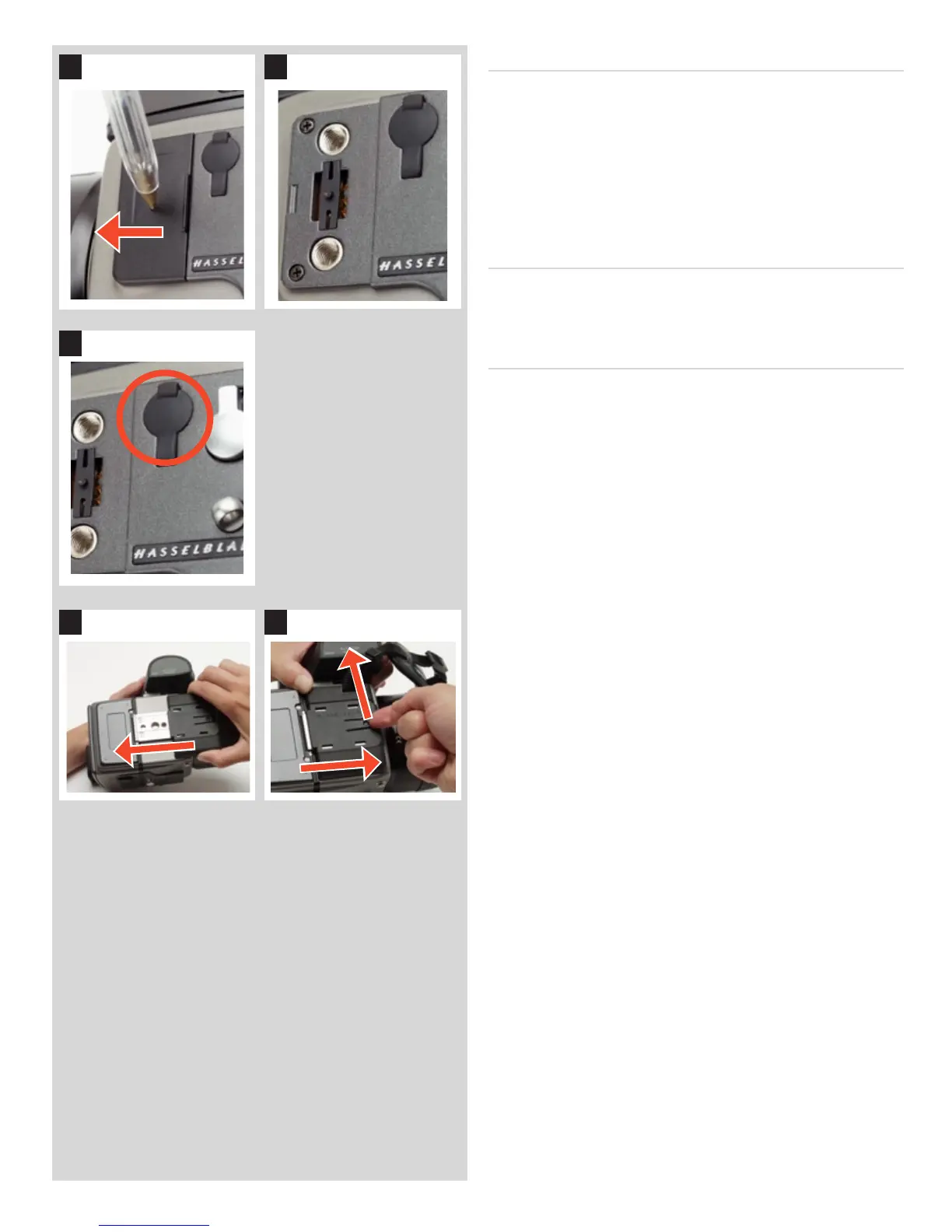
On the le hand side of the camera body are two accessory-retaining
screw threads (M5), as well as a databus connector, protected
beneath a cover.
e cover can be removed by inserting a pointed object, such as
a pen, in the small hole and then sliding it to the le, as in the il-
lustration. e cover-retaining clip can then also be removed to
access the connector.
PC-connector 20
A PC connector for non TTL-ash synchronisation is located on
the le side of the body. It is protected by a captive rubber plug.
Protective base plate 21, 22
To attach the protective base plate, slip it over the camera foot
until it stops. To remove it, li the securing catch while pushing
the plate back as in the illustration.
1918
20
2221
 Loading...