10
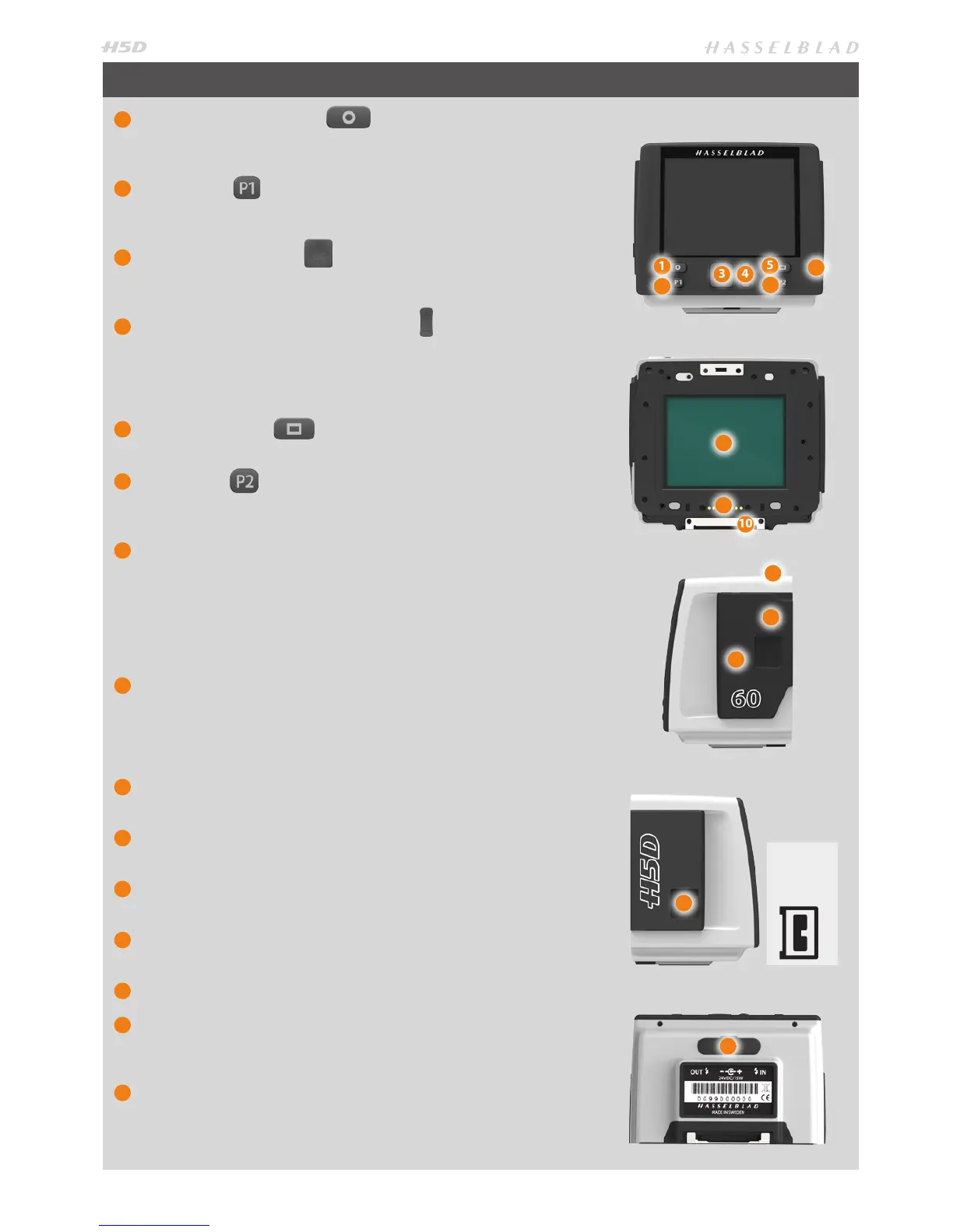
SENSOR UNIT
1
MENU / (EXIT) button
Opens and closes the menu system. Also used for various other tasks (EXIT
button, for example) as you issue commands navigating the menu system.
2
P1 button
Assignable button to access a specic function. Setting is made on sensor
unit or in the Camera Conguration tool in Phocus.
3
Navigation button
A four-way rocker button enabling you to browse images as well as navi-
gate the menu system.
4
Zoom- in/-out (Selection) button
Zoom-in /out rocker button for the preview image. You can zoom in to
view close-ups of previews for focus checking. You can zoom out to view
several at once and nally to view and select folders and media. Also acts
as a selection button for value setting on the sensor unit menu.
5
Display button
Steps through the various view modes for the preview image.
6
P2 button
Assignable button to access a specic function. Setting is made on sensor
unit or in the Camera Conguration tool in Phocus.
7
Ready-light
Indicates sensor unit condition. GREEN signies a new capture is possible
(steady or blinking). Blinking ORANGE signies the unit is busy (writing to
a CF card or sending data, for example) and so a new capture is not pos-
sible, although settings can be changed. Steady ORANGE signies the unit
is
in ‘sleep’ mode and requires a few seconds to re-activate.
RED signies a
problem (an explanatory message will be displayed).
8
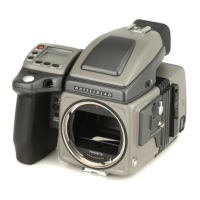
CCD and IR lter
The sensor is positioned behind a permanently mounted IR lter. Always
be very careful not to touch or scratch the surface of the lter when it is
exposed. Replace the protective cover whenever the sensor unit is not
mounted on a camera.
9
Databus connectors
For digital communication with camera body.
10
Retaining bar
Main support for sensor unit.
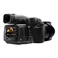
11
Safety catch
Prevents inadvertent removal of sensor unit.
12
‘Sensor plane’ index
For physical focus measurement in critical close-up work.
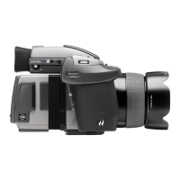
13
CF-card cover
14
FireWire port
For computer connection (please carefully note the orientation of the
FireWire plug when inserting into the sensor unit).
15
Flash sync and power connector ports
Flash sync ports and port for external power supply / battery adapter for
when the sensor unit is used with a view/large format camera. Protected
behind a rubber cover.
1
2
3 4
5
6
7
8
10
11
12
13
14
15
9
Previous H2/
H3/H4D users
please note the
orientation of the
plug on the H5D!