93
SEPARATE FLASH UNIT CONNECTION
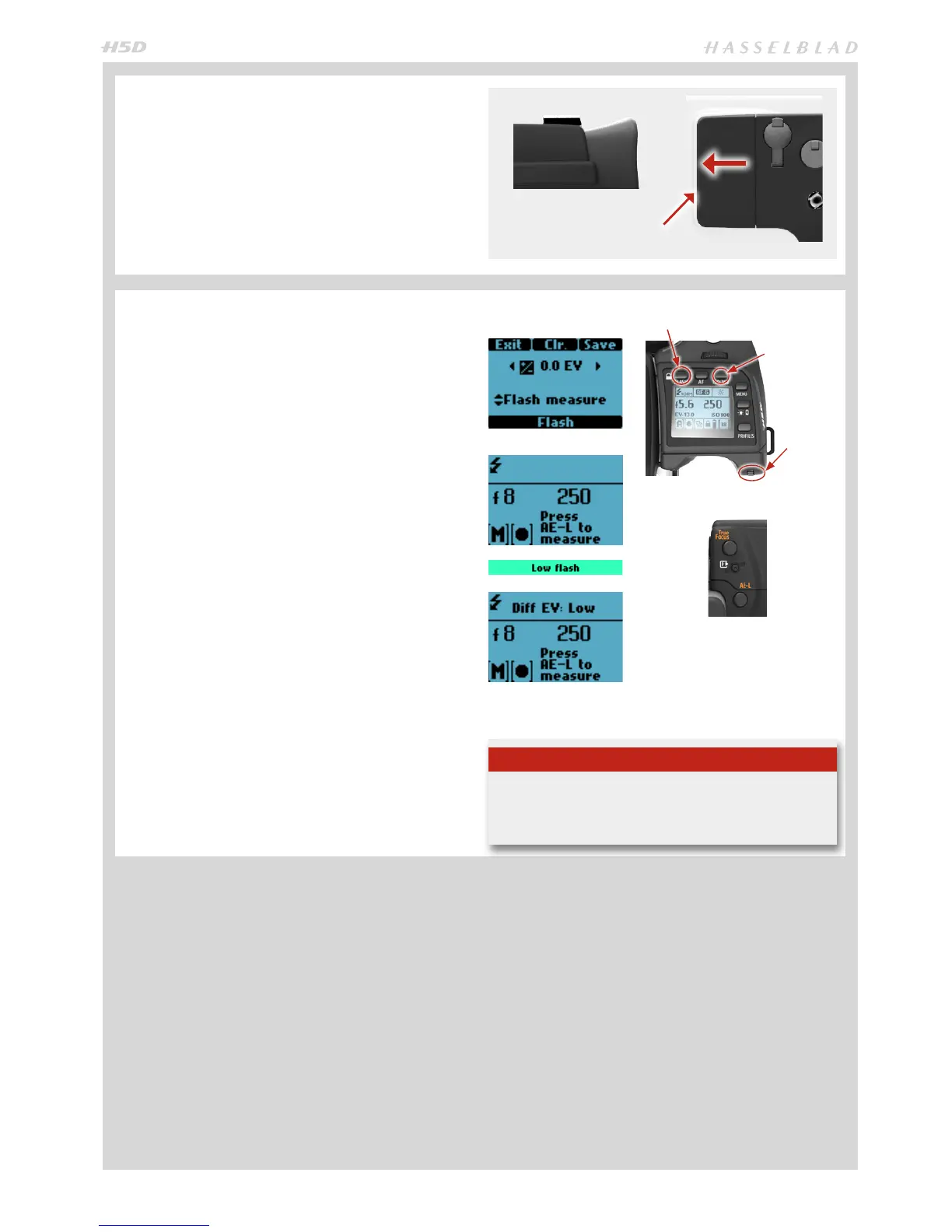
Separate ash units can be electrically connected either by
way of the hot shoe accessory holder (see previous warn-
ings) on the top of the viewnder or via a cord to the PC con-
nection port on the left hand side of the camera body. Slave
unit switches/ transmitters can also be connected similarly
dependant on unit (see specic user manuals for details).
Keep the plastic safety cover in place in the hot shoe when
not in use.
FLASH MEASURE OF SEPARATE
FLASH UNIT
You can measure the eect of an attached ash unit (with PC
connected ash units and SCA3902 compatible ash units
set to M mode), where the camera acts much as a ash me-
ter would. The aperture setting can be adjusted and more
trial exposures made until the information on the grip dis-
play is satisfactory.
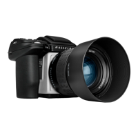
To use ash measure:
1) Press the FLASH button on the grip to access the ash
option screen.
2) Turn the Rear control wheel until Flash measure
appears.
3) Press Save (ISO/WB button) to access the ash expo-
sure screen.
4) Make preliminary required aperture setting by turning
the front control wheel.
5) Press the AE-L button. The camera will close the aper-
ture, raise the mirror and re the ash. Light reected
from the ash lit subject will be reected o a white spot
on the auxiliary shutter to the meter sensor.
6) Deviations from a normal exposure are displayed as
dierences in EV on the grip display and the viewnder
display. If ‘high’ or ‘low’ appears, change the aperture
accordingly and make a new test reading.
Change the aperture until Di EV: 0 appears, or the
desired amount of deviation from the normal exposure.
Di EV: Low signies more than 2 EV under
Di EV: High signies more than 2 EV over
Lift this edge of the cover rst
Tip
The ‘Low Flash’ warning can be turned o in Custom Option
#26 if preferred.
FLASH
SAVE
Rear scroll
wheel