IT 1002 Order No BA 93-66-1206 Issue 03.11.08 29
5.2.1 Drawn-Arc stud Welding with Ceramic Ferrule
Drawn-arc stud welding with ceramic ferrule is used with welding elements of 3 to 25 mm
diameter (preferably above 12 mm diameter) and with welding times of 50 to 2000 ms.
It is generally suitable for all welding positions. When stud welding with ceramic ferrule,
the welding position is PA (vertical). The major part of all applications applies to this
procedure.
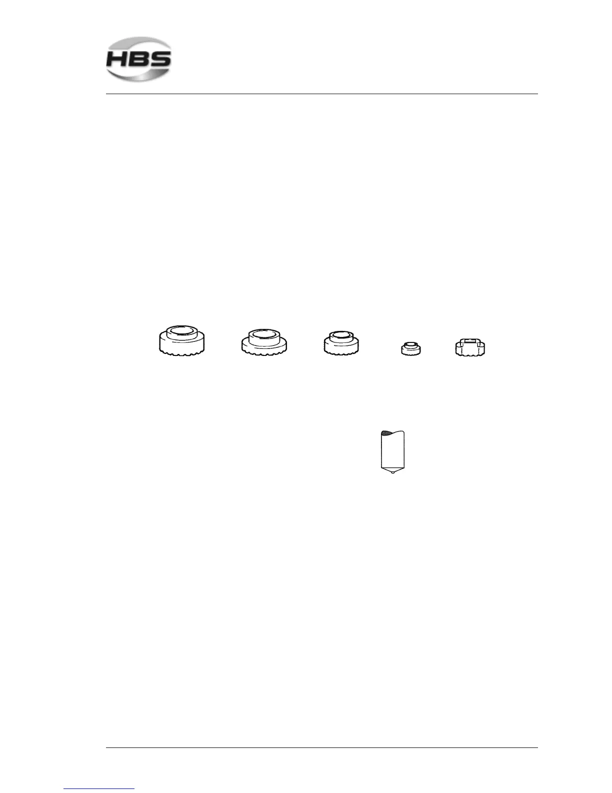
The ceramic ferrule (CF)
– prevents atmosphere from getting to the weld pool by a formation of metal vapor in
the arc chamber
– stabilizes and concentrates the arc, thus decreasing the arc blow effect
– forms the melt under pressure to a weld collar and supports the weld pool on a vertical
wall and overhead
– protects the welder from arc radiation and welding spatters.
Normally, the ceramic ferrule is used for only one weld and is removed after solidification
of the weld pool.
Standard welding elements and ceramic ferrules are described in several standards (see
appendix). When using concrete anchors or shear connectors the front area can be
plane constructed with a small pressed-in aluminum ball.
Studs with cone-shaped front area and aluminum ball are preferably used with
ceramic ferrule.
5 Stud Welding Procedure
5.2 Functional Principle of Stud Welding