DAC-42(A)-x-PN
Page 65
DAC-42(A)-x-PN
Manual
Revision: 1.0
22.01.2024
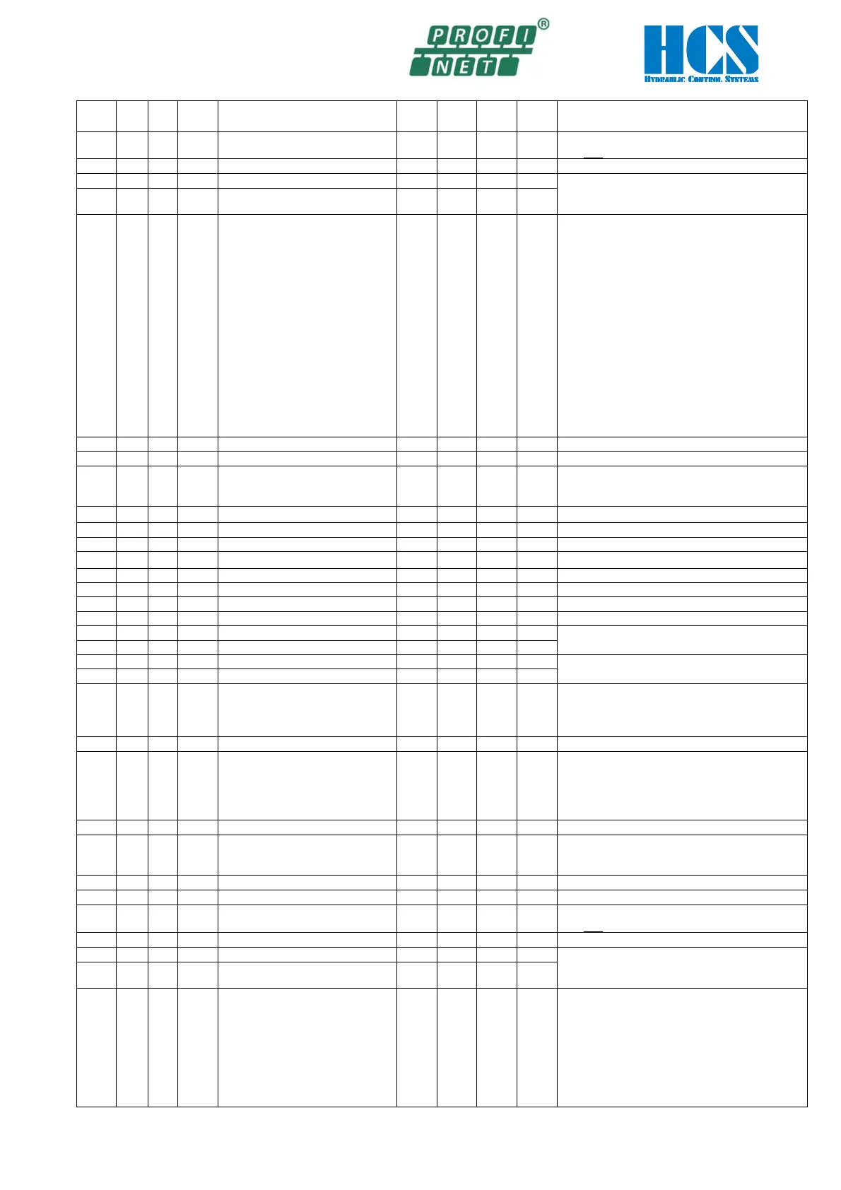
ID
Hex
ID
dec
W/R
Nam
Function Unit
Min
Max
Def
Description
0x2E
46 R/W
C1.05
Set value sign and gain V/V -400
400
100
100 == Factor 1.00
1000 == 1.000 V
9.999 V = max. current depending on solenoid
0x31
49 R/W
C1.08
Dead band compensation B V 0
9999
0
0x32
50 R/W
C1.09
Sensor type
Attention:
No negative controller output
possible when 10, 11 or 12 is
selected!
--- 1
28
4
off = Deactivated
1 = 0...20mA
2 = 4...20mA
3 = 12mA +-8mA
4 = 0...10V
5 = 0...+-10V
6 = 6V +-2.5V
7 = 7.5V +-2.5V
8 = 6V +-5V
9 = 7,5 +-5V>
10 = 0..20mA (positive contr. outp. only)
11 = 4..20mA (positive contr. outp. only)
12 = 0..10V (positive contr. outp. only)
13 = reserved
14 = 5V+-3.0V
15..27 = reserved
0x35
53 R/W
C1.12
Actual value sign --- - 1
+ 1
1
- 1 = negative
0 = off
0x36
54 R/W
C1.13
P-Portion K
V/V 0
400
0
100 == Factor 1.00
Portion for PT1 (to C1.16)
0x39
57 R/W
C1.16
P-Portion K
V/V 0
400
0
100 == Factor 1.00
-1000 == -1.000 V; 1000 == 1.000 V
Comparator delay into window
1 == 10 ms
0 == no delay
Comparator delay out of window
0x42
66 R/W
C1.25
Comparator selection COMP_1 --- 0
3
0
0 = off
1 = Set value
2 = Actual value
Cable fracture detection feedback
0x44
68 R/W
C2.00
Controller selection --- 0
4
0
0 = off
1 = P-PT
1
-I-DT
1
2 =Remote
3 =dff
0x46
70 R/W
C2.02
Linearization --- 0
6
0
0 = linear
1 ... 5 = standard curves
0x49
73 R/W
C2.05
Set value sign and gain V/V -400
400
100
100 == Factor 1.00
1000 == 1.000 V
9.999 V = max. current depending on solenoid
0x4C
76 R/W
C2.08
Dead band compensation B V 0
9999
0
0x4D
77 R/W
C2.09
Sensor type
Attention:
No negative controller output
possible when 10, 11 or 12 is
selected!
--- 0
12
4
off = Deactivated
1 = 0...20mA
2 = 4...20mA
3 = 12mA +-8mA
4 = 0...10V
5 = 0...+-10V
6 = 6V +-2.5V
7 = 7.5V +-2.5V