DAC-42(A)-x-PN
Page 68
DAC-42(A)-x-PN
Manual
Revision: 1.0
22.01.2024
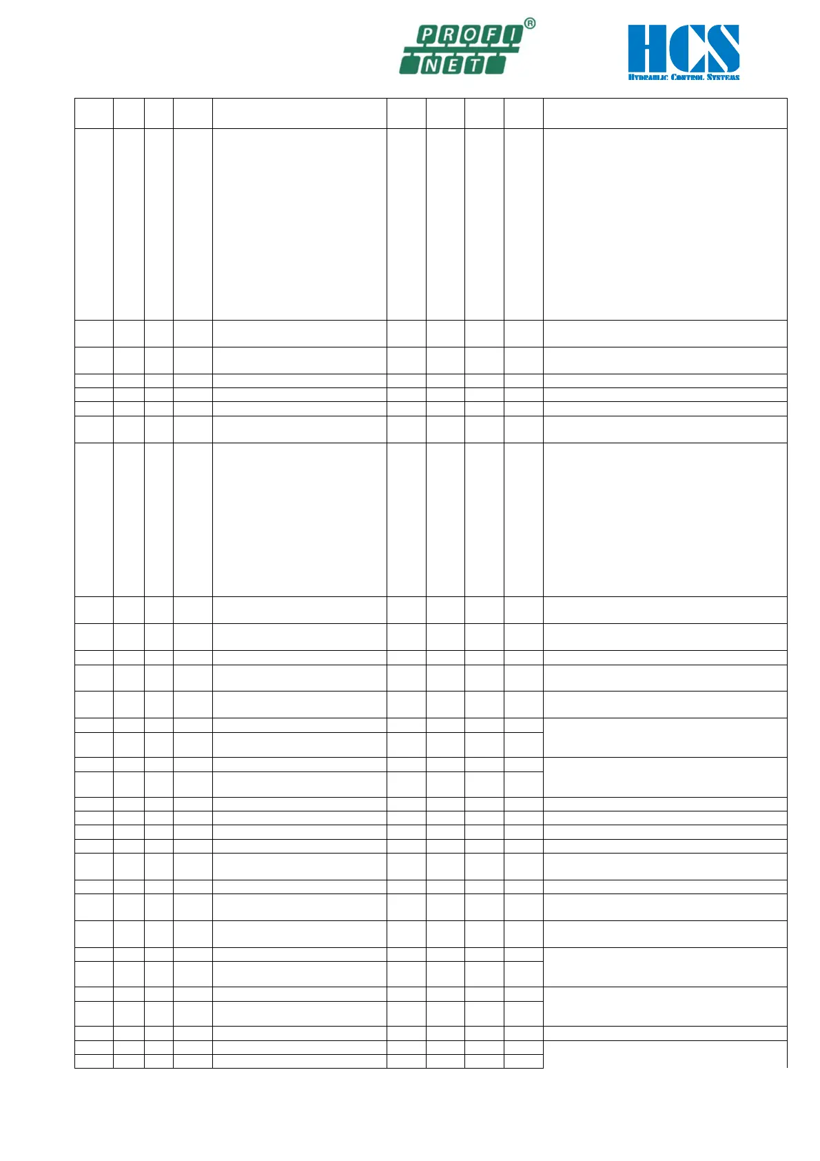
ID
Hex
ID
dec
W/R
Nam
Function Unit
Min
Max
Def
Description
0xB0
176 R/W
E Int
Internal Digital Switches
(Read/Set)
--- 0
0
xFFFF
0x0001 = Din_1 active (Read/Write)
0x0002 = Dout_1 active (Read only )
0x0004 = Comp_1 active (Read only )
0x0008 = reserved
0x0010 = Din_2 active (Read/Write)
0x0020 = Dout_2 active (Read only )
0x0040 = Comp_2 active (Read only )
0x0080 = reserved
0x0100 = Input SP1 active (Read only )
0x0200 = Input SP2 active (Read only )
0x0400 = Enable active (Read only )
0x0800 = Error active (Read only )
0x1000 = Input SP3 active (Read only )
0x2000 = Input SP4 active (Read only )
0x8000 = Bus Disable Card (Read/Write)
0xB1
177 R/W
E 23
Profinet telegram timeout window
S 0
9999
0
0 == function deactivated
0xB2
178 R/W
E 26
Profinet Timeout Error handling --- 0
1
0
0 = Blinking Enable Led shows Profinet timeout
1 = Profinet timeout causes error.
0 == 0.000 V; 9999 == 9.999 V
0 == 0.000 V; 9999 == 9.999 V
0xD2
210 R/W
E 31 Mode of the analog output --- 1
2
2
1 = Voltage output at pin 10b
2 = Current output at pin 10b.
0xD3
211 R/W
E 32 Selection set point S1.07 (U/I)
--- 0
11
1
off = Deactivated
1 = Voltage -10V..+10V
2 = Voltage 0..10V
3 = Voltage 5V+-5V
4 = Voltage 5V+-4.5V w/o signal observation
5 = Voltage 5V+-4.5V with signal observation
6 = 0..20mA w/o cable fract. det.
7 = 10+-10mA w/o cable fract. det.
8 = 4..20mA w/o cable fract. det.
9 = 4..20mA with cable fract. det.
10 = 12+-8mA w/o cable fract. det.
8mA with cable fract. det.
0xD4
212 R/W
E 33 Offset for analog voltage output
(depends on HW + SW version)
V -9999
9999
0
-1000 == -1.000 V; 1000 == 1.000 V
0xD5
213 R/W
E 34 Offset for analog current output
(depends on HW + SW version)
mA -9999
9999
0
-1000 == -1.000 mA; 1000 == 1.000 mA
0xDA
218 R/W
C1.36
Sensor signal correction factor for
V/V -100
100
100
100 == Factor 1.00
0xDB
219 R/W
C2.36
Sensor signal correction factor for
V/V -100
100
100
100 == Factor 1.00
Spool overlap compensation A
1000 == 1.000 V
9.999 V = max. current depending on solenoid
0xDD
221 R/W
C1.38
Spool overlap compensation B V 0
9999
0
Spool overlap compensation A
1000 == 1.000 V
9.999 V = max. current depending on solenoid
0xDF
223 R/W
C2.38
Spool overlap compensation B V 0
9999
0
Factor analog output current
0xD4
212 R/W
E 33
Offset for analog output
(depends on HW + SW version)
V -9999
9999
0
-1000 == -1.000 V; 1000 == 1.000 V
0xDA
218 R/W
C1.36
Sensor signal correction factor for
V/V -100
100
100
100 == Factor 1.00
0xDB
219 R/W
C2.36
Sensor signal correction factor for
V/V -100
100
100
100 == Factor 1.00
Spool overlap compensation A
1000 == 1.000 V
9.999 V = max. current depending on solenoid
0xDD
221 R/W
C1.38
Spool overlap compensation B V 0
9999
0
1000 == 1.000 V
9.999 V = max. current depending on solenoid
0xDF
223 R/W
C2.38
Spool overlap compensation B V 0
9999
0
Linearization curve branch 1 [0,0]
1000 == 1.000 V
Linearization curve [0,0]