EasyManua.ls Logo

Heart Interface LINK 1000 User Manual

Heart Interface LINK 1000
44 pages
To Next Page IconTo Next Page
Page #1 background imageLoading...
Page #1 background image
02/11/98
1
Manual Part # 890030
INSTALLER NOTE: LEAVE THIS MANUAL WITH THE OWNER.
IT CONTAINS IMPORTANT OPERATING INFORMATION.
This manual applies to Link 1000 with serial number above 1900.
APPLICATIONS: The
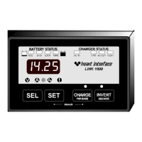
Link 1000
is an instrumentation and control panel
designed for use with Heart Interface
Freedom
series inverter/chargers
operated with a single battery bank. For installations with a
Freedom
inverter/charger and two battery banks, the
Link 2000
is recommended.
For instrumentation of a single battery bank (no inverter control) the
Link 10
is recommended, while the
Link 20
is recommended for instrumention of a
two battery bank system (no inverter control).
OPERATION: Instructions how to operate your
Link 1000
begin on page 4
of this manual.
INSTALLATION: This manual contains easy to follow installation instructions
beginning on Page 37.
WARRANTY ISSUES: Warranty issues should be directed to Heart Interface.
Please do not route warranty issues through your dealer. See Page 36.
21440 68
th
Ave. So. Kent, WA 98032
(253) 872-7225 Toll Free 1-800-446-6180
Link1000Revc.pm6
OWNER'S MANUAL
LINK 1000
TC2+2
COMPATIBLE

Table of Contents

Question and Answer IconNeed help?

Do you have a question about the Heart Interface LINK 1000 and is the answer not in the manual?

Heart Interface LINK 1000 Specifications

General IconGeneral
BrandHeart Interface
ModelLINK 1000
CategoryControl Panel
LanguageEnglish

Summary

Link 1000 Technical Specifications

Electrical and Measurement Specifications

Covers voltage, current, power, ranges, resolution, and accuracy.

Important Information and Warnings

Power Connection Warnings

Critical safety warnings for connecting power to the Freedom inverter/charger and Link 1000.

Inverter and Charger Operations

Charge and Invert Functionality

Explains how to activate and the conditions for the charging and inverter functions.

Advanced Operational Modes

Power Share and Idle Mode

Explains Power Share for load management and Idle Mode for power saving.

Battery Capacity Testing

Procedure for Capacity Testing

Outlines the step-by-step process for testing battery capacity using the Link 1000.

Ideal Battery Charging

The Ideal Charge Curve

Describes the four charge cycles (Charge, Acceptance, Float, Equalize) and their graphical representation.

Battery Equalizing Process

Equalizing Lead-Acid and Gel Batteries

Details the procedure for equalizing lead-acid batteries and considerations for gel batteries.

Critical Equalizing Cautions

Highlights essential safety precautions and potential damage from improper equalizing.

System Setup Procedures

Accessing and Navigating Setup

Explains how to enter and move through the Set Up and Advanced Functions modes.

Setting Charged Parameters

Charged Parameters Explained

Defines Charged Voltage and Charged Current Percent for accurate battery state monitoring.

Configuring Battery Settings

Setting Charged Voltage

Provides step-by-step instructions for adjusting the Charged Voltage parameter.

Setting Charged Current Percentage

Details the procedure to change the Charged Current Percentage setting.

Setting Battery Capacity

Procedure for Setting Capacity

Guides users on setting the correct battery capacity in Amp-hours for accurate readings.

System Configuration Options

Function F10: Battery Type Selection

Sets battery type for charge voltages and Peukert exponent.

Resetting the Link 1000 Unit

Accessing Reset Functions

Explains how to access reset functions for Amp-hours or all settings.

Setting Peukert's Exponent

Understanding Peukert's Exponent

Explains the exponent's role in battery capacity and time remaining calculations.

Procedure to Set Peukert's Exponent

Step-by-step guide for setting the exponent, considering battery type.

Peukert's Equation and Discharge Rates

Effect of High Discharge Rates

Discusses how discharge rates affect battery capacity according to Peukert's Equation.

Calculating Peukert's Exponent

Details how to calculate the exponent using discharge tests and the provided formula.

Peukert Exponent Calculation Example

Calculating Peukert's Exponent Example

Demonstrates the calculation of the Peukert exponent using a specific battery example.

Link 1000 Error Codes

Inverter and Battery Errors (E01-E03)

Explains error codes related to inverter voltage, temperature, and battery overload.

System and Charging Faults (E04-E09)

Details error codes for battery overload, AC backfeed, electronic overload, charging circuit, and spares.

Link 1000 Error Code Clarifications

Operational Errors and Warnings (E10-E15)

Explains error codes for depowered state, voltage sense, AC polarity, and out-of-range readings.

Wiring Preparations and Notes

General Wiring and Shunt Notes

Provides guidelines on wire gauge, NEC/ABYC compliance, shunt integrity, and handling high currents.

Battery Compartment Wiring Detail

Link 1000 Terminal Connections

Wire-by-Wire Wiring Verification

Initial Startup Procedure