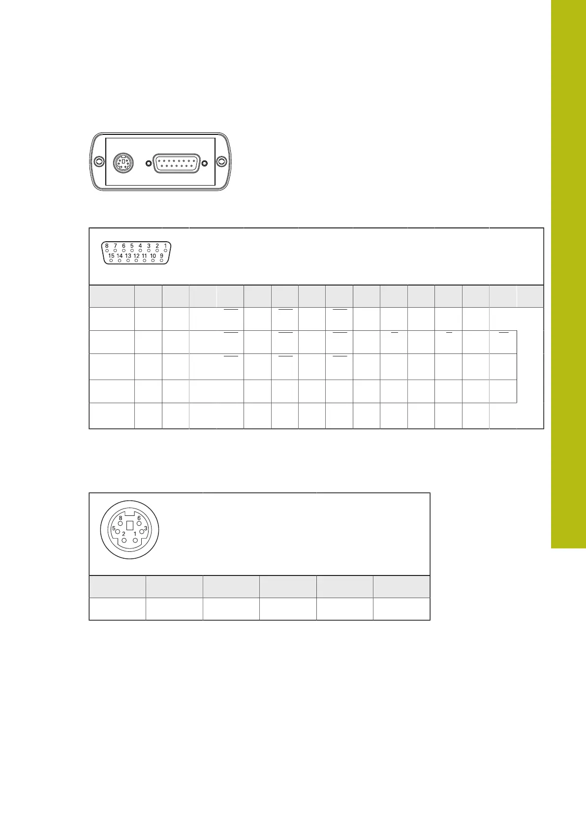
RENCO R35i/R35iL pin layout |
5 RENCO R35i/R35iL pin layout
X1
4 2 1 9 3 11 14 7 13 5 15 8 6 10 12
LD/0 U
P
0 V U
a1
U
a1
U
a2
U
a2
U
a0
U
a0
/ / / / / /
LD/LD U
P
0 V U
a1
U
a1
U
a2
U
a2
U
a0
U
a0
U U V V W W
LD/PP U
P
0 V U
a1
U
a1
U
a2
U
a2
U
a0
U
a0
U / V / W /
PP/0 U
P
0 V U
a1
/ U
a2
/ U
a0
/ / / / / / /
PP/PP U
P
0 V U
a1
/ U
a2
/ U
a0
/ U / V / W /
Test
pin
Shield on housing; U
P
= Power supply.
Vacant pins or wires must not be used.
X2
1 2 3 5 6 8
/ / / U / GND
Shield on housing.
Vacant pins or wires must not be used.
5
HEIDENHAIN | PWT 101 Block Commutation Module | User's Manual | 07/2021
41

 Loading...


