154 6 Programming: Programming Contours
6.5 Path Contours — Polar Coordinates
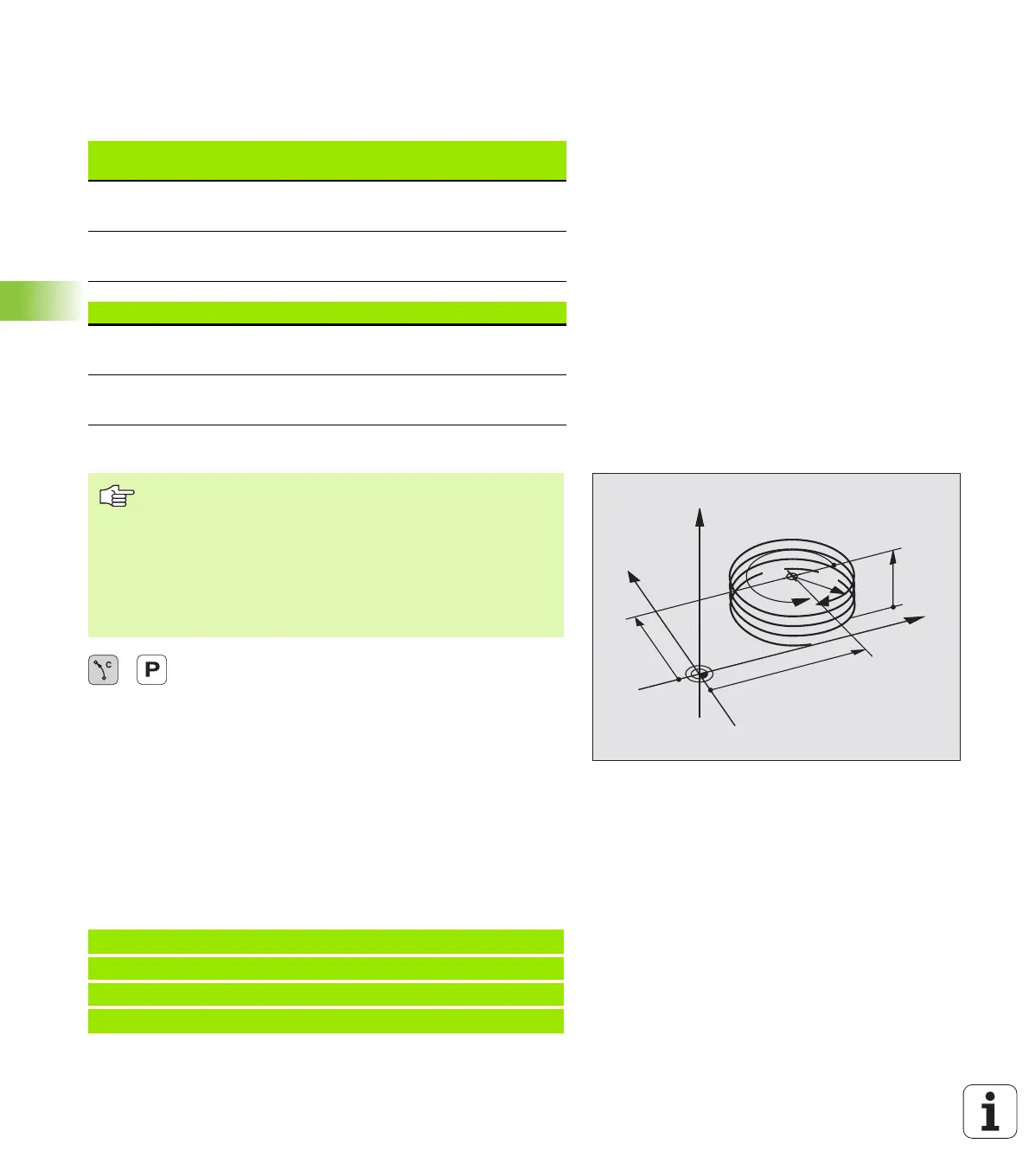
Shape of the helix
The table below illustrates in which way the shape of the helix is
determined by the work direction, direction of rotation and radius
compensation.
Programming a helix
U Polar coordinates angle: Enter the total angle of
tool traverse along the helix in incremental
dimensions. After entering the angle, identify the
tool axis with an axis selection key.
U Coordinate: Enter the coordinate for the height of the
helix in incremental dimensions.
U Direction of rotation DR
Clockwise helix: DR–
Counterclockwise helix: DR+
U Radius compensation RL/RR/R0
Enter the radius compensation according to the table
above.
Example NC blocks: Thread M6 x 1 mm with 5 revolutions
Internal thread
Work
direction
Direction
Radius
comp.
Right-handed
Left-handed
Z+
Z+
DR+
DR–
RL
RR
Right-handed
Left-handed
Z–
Z–
DR
DR+
RR
RL
External thread
Right-handed
Left-handed
Z+
Z+
DR+
DR–
RR
RL
Right-handed
Left-handed
Z–
Z–
DR
DR+
RL
RR
Always enter the same algebraic sign for the direction of
rotation DR and the incremental total angle IPA. The tool
may otherwise move in a wrong path and damage the
contour.
For the total angle IPA, you can enter a value from
–5400° to +5400°. If the thread has more than 15
revolutions, program the helix in a program section repeat
(see “Program Section Repeats,” page 344)
12 CC X+40 Y+25
13 L Z+0 F100 M3
14 LP PR+3 PA+270 RL F50
15 CP IPA-1800 IZ+5 DR-
Y
X
Z
25
40
5
270°
R3
CC
 Loading...


