59
8
Appendix
8.1
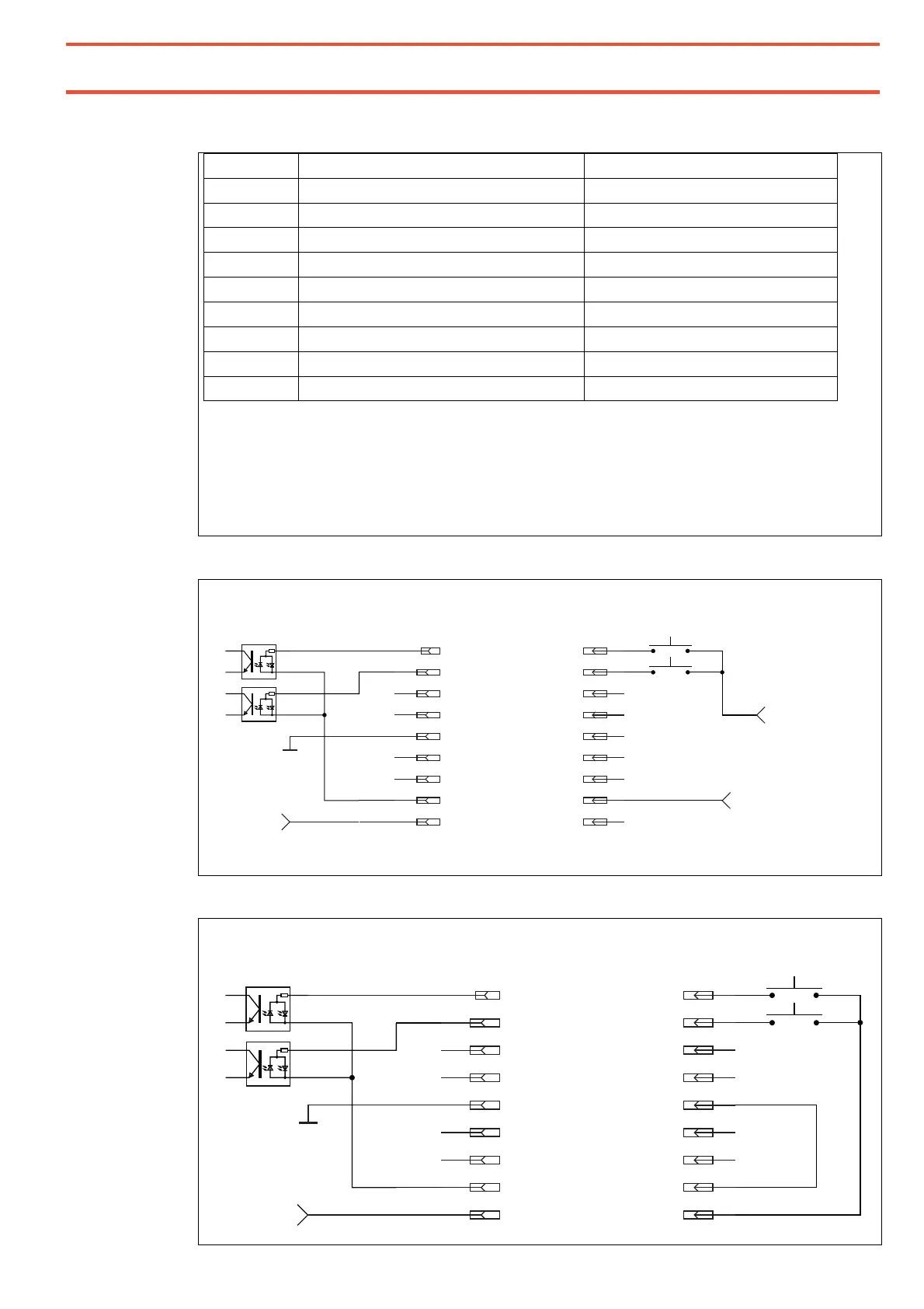
Interface XS1 START
Pin no.: Function Addition
1 Start X input Optocoupler input
2 Start Y input Optocoupler input
3
4
5 Internal ground output
6
7
8 Input potential for all optocoupler inputs
9 Internal output +24V
Pins 5 and 9 are used for querying pushbuttons, switches etc.
The internal power supply is rated for a maximum of 50 mA. Under no circumstances may a
power supply be connected to these outputs!
The optocoupler inputs can be connected to +24 V or alternatively to ground.
The corresponding counter potential is connected for all inputs of this interface
together to pin 8.
Example: Starting RC15 with external voltage
Example: Starting RC15 with dry contact outputs
1
2
3
4
5
6
7
8
9
1
2
3
4
5
6
7
8
9
+24VDC,
50 mA
RC15 DC Drive
Controller Input
PLC / Robot
Output
+24VDC output
Start X
Start Y
+0VDC output
Common potential inputs
Ground
1
2
3
4
5
6
7
8
9
1
2
3
4
5
6
7
8
9
+24VDC,
50 mA
RC15 DC Drive
Controller Input
PLC / Robot
Output
Start X
Start Y
Ground
+24VDC, 20 mA
+0VDC
Do not connect external 24VDC to pin 5 and pin 9!
Common potential inputs