61
8
Appendix
8.3
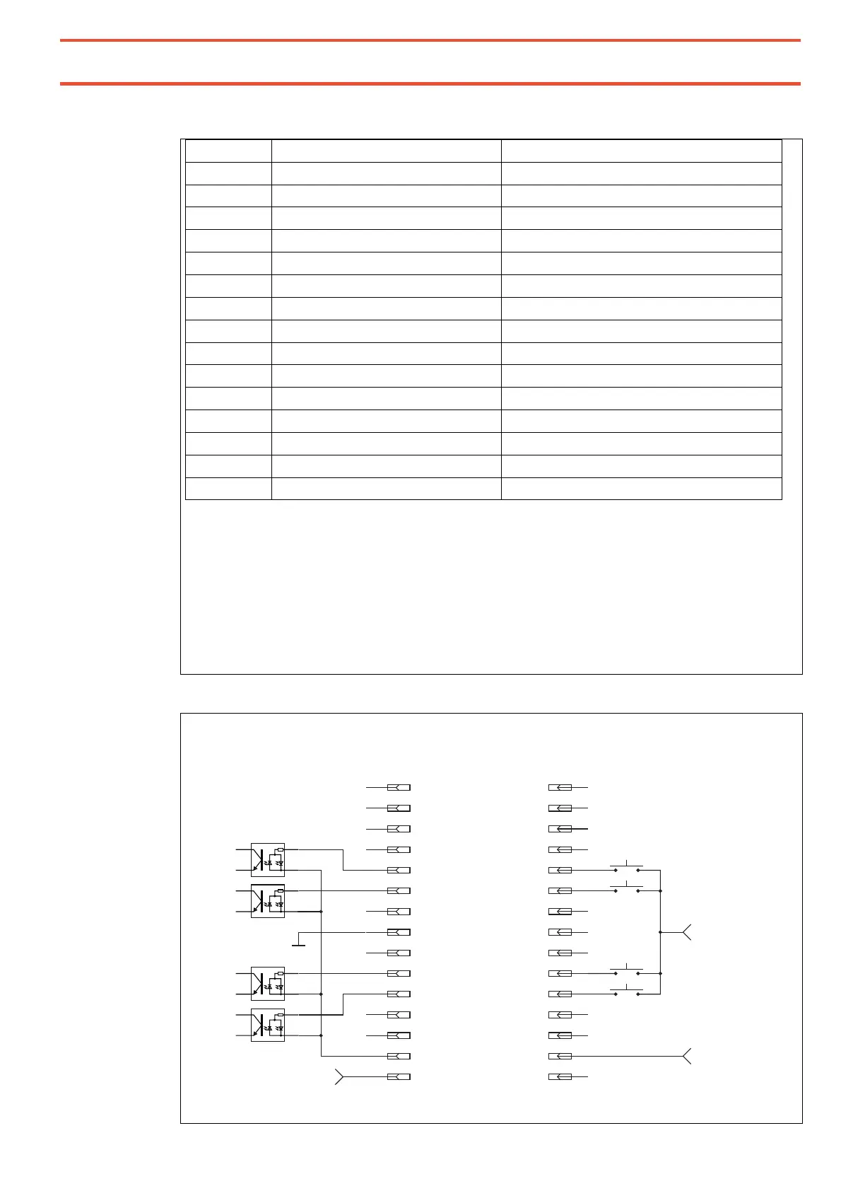
Interface XS10 PLC, Robot
Pin no.: Function Addition
1 Output: Device ready for dosing Optocoupler output
2 Reserved, do not assign!
3 Output: fault Optocoupler output
4 Reserved, do not assign!
5 Start X input Optocoupler input
6 Start Y input Optocoupler input
7
8 Internal ground output
9 Input: Potential for all outputs
10 Input: Reset fault Optocoupler input
11 Start Z input Optocoupler input
12 Output: Refill tank Optocoupler output
13 Output: Tank empty Optocoupler output
14 Input: Potential for all optocoupler inputs
15 Output: internal +24V supply
The internal power supply on Pin 8 and 15 is intended for reading in external dry contacts. It is
rated for a maximum of 50 mA.
Do NOT connect a power supply or heavier loads to these outputs!
The optocoupler inputs can be connected to +24 V or alternatively to ground.
The corresponding counter potential is connected for all inputs of this interface
together to Pin 14.
The optocoupler outputs can be supplied for the query with internal or
external (5-24 V DC) voltage. They switch through the potential applied
to Pin 9 (max. 50 mA).
Example: Input external voltage, positive rail switched
1
2
3
4
5
6
7
8
9
10
11
12
13
14
15
1
2
3
4
5
6
7
8
9
10
11
12
13
14
15
+24VDC,
50 mA
internal Ground
external
+24VDC
Start X
Start Y
Start Z
Reset
Reset Error
RC15 DC Drive
Controller Input
PLC / Robot
Output
Start X
Start Y
Start Z
Ground output
external Ground
Do not connect!
Do not connect!
Do not connect external 24VDC to pin 15!
Common potential inputs