HD2579Y
TIP:
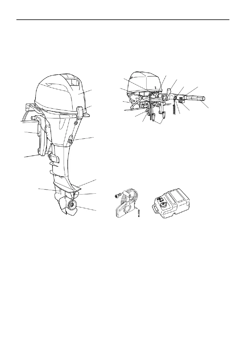
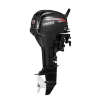
Components diagram
* May not be exactly as shown; also may not be included as standard equipment on all mod-
els (order from dealer).
F15HE, F15HE/T, F20HE, F20EHA, F20FE/T, F20HE/T
21
9
10
20
11
12
19
18
17
16
20
15
14
13
9
14
4
19
18
16
22
23
5
6
ZMU07412
1. Top cowling
2. Cowling lock lever
3. Drain screw
4. Anti-cavitation plate
5. Trim tab
6. Propeller
7. Cooling water inlet
8. Clamp bracket
9. Alert indicator(s)
10. Gear shift lever*
11. Engine stop button/Engine shut-off
switch*
12. Throttle friction adjuster*
13. Throttle grip*
14. Power tilt switch*
15. Clip*
16. Clamp screw
17. Steering friction lever*
18. Restraint cable attachment
19. Tilt support knob*
20. Flushing device
21. Starter button*
22. Remote control box (side mount type)*
23. Fuel tank*