allowed to enter the fuel tank while operating
1
2
the engine.
HD26181
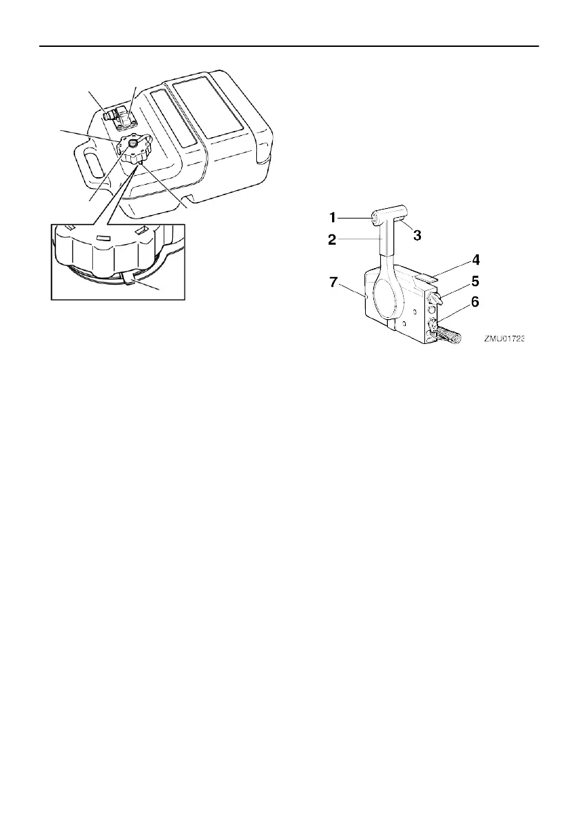
Remote control box
4
The remote control lever actuates both the
shifter and the throttle. The electrical
switch- es are mounted on the remote
control box.
5
3
3
1. Fuel joint
2. Fuel gauge
3. Pressure relief tab
4. Fuel tank cap
5. Air vent screw
Fuel joint
ZMU0744
2
1. Power tilt switch
2. Remote control lever
3. Neutral interlock trigger
4. Neutral throttle lever
5. Main switch
6. Engine shut-off switch
This joint is used to connect the fuel line.
Fuel gauge
This gauge shows the approximate amount
of fuel remaining in the fuel tank.
Pressure relief tab
This is attached to the filler hole of the fuel
tank.
Fuel tank cap
This cap seals the fuel tank. To loosen the
cap, press and hold the pressure relief tab
and turn the cap counterclockwise.
HD43141
Air vent screw
This screw is on the fuel tank cap. When
turning the air vent screw counterclockwise,
it is loosened and the pressure in the fuel
tank is released to a certain pressure. Air is
7. Throttle friction adjuster
Remote control lever
Moving the lever forward from the neutral
po- sition engages forward gear. Pulling the
le- ver back from neutral engages reverse.
The engine will continue to run at idle until
the le- ver is moved about 35 (a detent can
be felt). Moving the lever farther opens the
throttle, and the engine will begin to
accelerate.