VC3000Pro Series Vision Controller User Manual
4
2.2.1 Light Source Extended Module
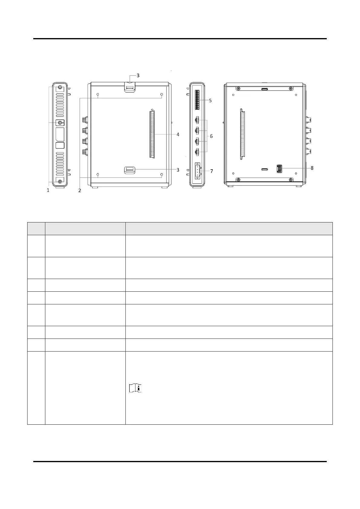
Figure 2-2 Light Source Extended Module Appearance
Table 2-2 Appearance Description of Light Source Extended Module
It is used to fix the extended module, and you should use M3 or M4
screw.
It is used to connect with the main module or another extended
module.
It is used to connect another extended module.
It is used to connect the plug of extended module.
Light Source Trigger
Interface
It is used to trigger external devices via this interface.
It is used to connect light source.
It provides power supply for light source extended module.
It is used to switch the serial port No. The serial port No. ranges from
COM 11 to COM 12, and the corresponding DIP switch No. is from 5
to 6.
Note
If you have multiple extended modules, the DIP switch takes effect
only when you set 1 DIP switch No. to ON of each module, and the
ON DIP switch No. is different among modules.
 Loading...