VC3000Pro Series Vision Controller User Manual
11
Chapter 4 Interface Description
4.1 Main Module Interface
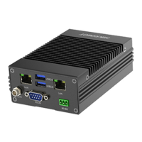
4.1.1 Power Interface
The device’s power interface is used to connect the power adapter. On the left side of the power
interface has two 0 V connectors, you can select one to connect power supply negative. On the right
side of the power interface has two 24 V connectors, you can select one to connect power supply
positive.
Figure 4-1 Power Interface
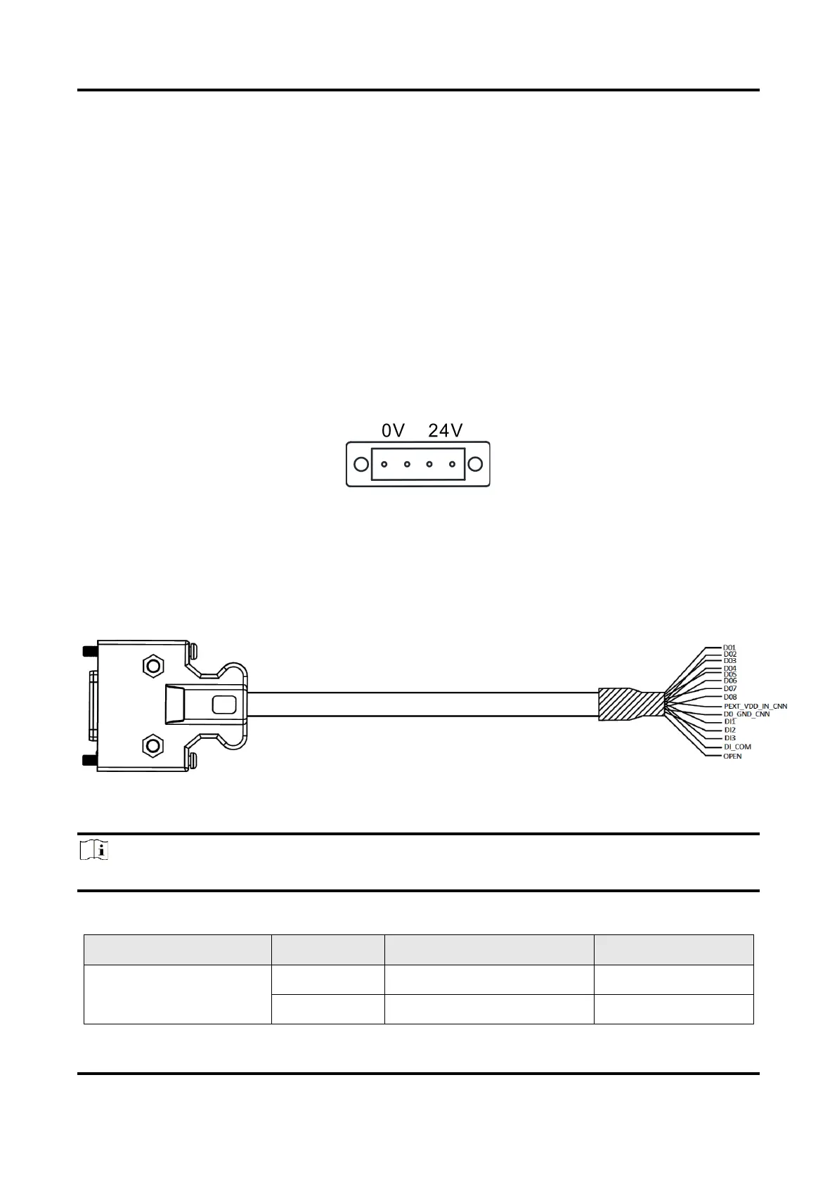
4.1.2 GPIO Interface
The main module supports 11-channel GPIO and NPN/PNP switching for output. You need to use
following GPIO cable when using GPIO interface.
Figure 4-2 GPIO Cable
The device’s GPIO Interface has 15 pins, and you can refer to the following table for pin definitions.
Note
You should refer to the table below and the label attached to GPIO cable when wiring.
Table 4-1 Pin Definitions of GPIO Interface
 Loading...