VC3000Pro Series Vision Controller User Manual
20
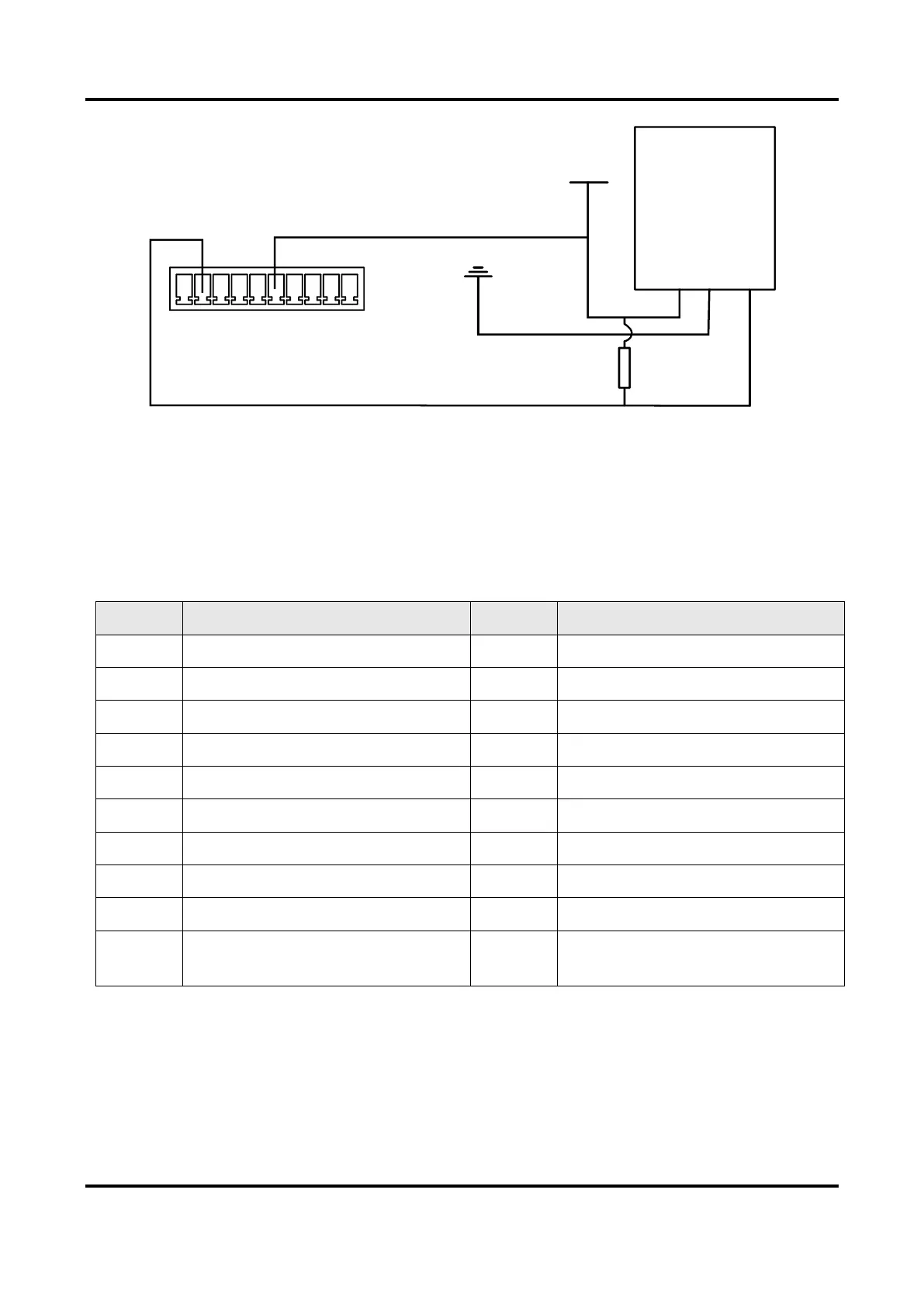
NPN
Power Supply
Ground
Signal Ground
R
VCC
Power Supply
U- 1- 2- 3- 4- 1+ 2+ 3+ 4+ U+
Figure 4-16 NPN Device Controlling Light Source
4.2.2 IO Extended Module Interface
The IO extended module supports 16-channel GPIO and NPN/PNP switching for output. The GPIO
interface has 20 pins, and you can refer to the following table for pin definitions.
Table 4-3 Pin Definitions of GPIO Interface
Opto-isolated input signal ground
Opto-isolated output signal ground
Opto-isolated input signal ground
Opto-isolated output external
interface
Opto-Isolated Input Wiring
Regarding opto-isolated input, different input electrical level types correspond to varied voltage
ranges.
●
When the input electrical level type is high electrical level, the voltage range is from 4 V to 24 V.
 Loading...