VC3000Pro Series Vision Controller User Manual
25
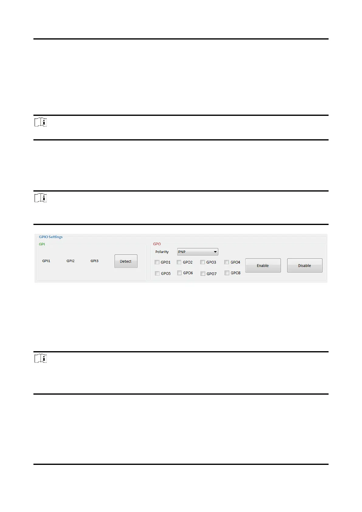
5.2 Set Main Module
The GPIO settings allows you to detect the electrical level of the input signal, set output polarity,
enable high or low electrical level, etc.
Input Settings
Go to GPI, click Detect, and you can view the electrical level of the input port.
Note
Red color stands for the high electrical level, and green color stands for the low electrical level.
Output Settings
Go to GPO, and select PNP or NPN as Polarity according to actual demands. Check the specific
output port, and click Enable or Disable to enable high electrical level or low electrical level
correspondingly according to actual demands.
Note
If you click Enable, the output port you selected will turn into red color. If you click Disable, it will
turn into green color.
Figure 5-2 Set Main Module
5.3 Set Light Source Extended Module
The light source extended module settings allows you to set light source related parameters. You
can select specific light source port, set its duration and brightness, etc.
Note
Make sure that the light source extended module has connected to the main module first, and the
connection has been set up between the light source extended module and the main module via
Initial Connection before setting light source parameters.
Go to Extended Light Source Settings, select Port, and set Duration and Brightness according to
actual demands.
Regarding Status, you can check On or Off to let the light source turn on or turn off after receiving
a trigger signal that can be Rising Edge or Falling Edge. Click Apply after setting light source
parameters.
 Loading...