VC3000Pro Series Vision Controller User Manual
2
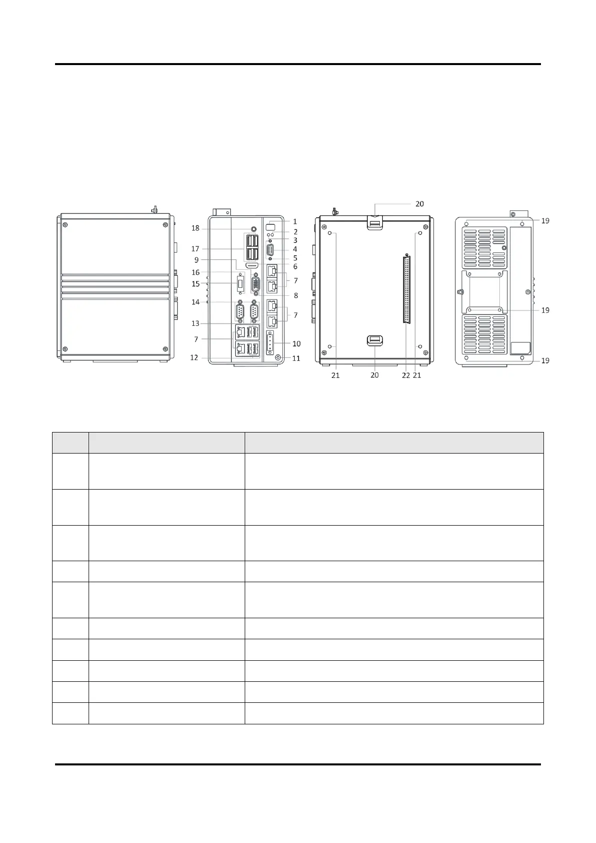
Chapter 2 Appearance
2.1 Main Module Appearance
Figure 2-1 Main Module Appearance
Table 2-1 Main Module Appearance Description
It is used to power on/off the device. Press it shortly to
power on the device, and long press it for 4 s to power off.
It indicates device power status. The indicator is solid
green when the device is switched on.
It indicates HDD status. The indicator is flashing red when
the HDD reads and writes data.
It provides input and output function.
Screw Hole for GPIO
Interface
It is used to fix GPIO interface.
It is used to transmit audio and video signals.
It is used to transmit network signal.
It is used to transmit video signal.
Screw Hole for VGA Interface
It is used to fix VGA interface.
It provides power supply.
 Loading...