EasyManuals Logo

HikRobot VC3000Pro Series User Manual

Default Icon
39 pages
To Next Page IconTo Next Page
To Previous Page IconTo Previous Page
Page #28 background imageLoading...
Page #28 background image
VC3000Pro Series Vision Controller User Manual
21
When the input electrical level type is low electrical level, the voltage range is from 0 V to 3 V.
Note
Wiring may differ when connecting the GPIO interface of IO extended module to different types
of external devices.
You can design circuit diagram for other external devices according to the diagrams below.
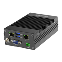
PNP Device
When connecting the GPIO interface of IO extended module to PNP device, it is recommended to
use 4.7 kΩ pull-down resistor.
PNP
Power Supply
Ground
Signal Cable
R
VCC
Power Supply
DI
COM
COM
8 7 6 5 4 3 2 1
Figure 4-17 Connect to PNP Device
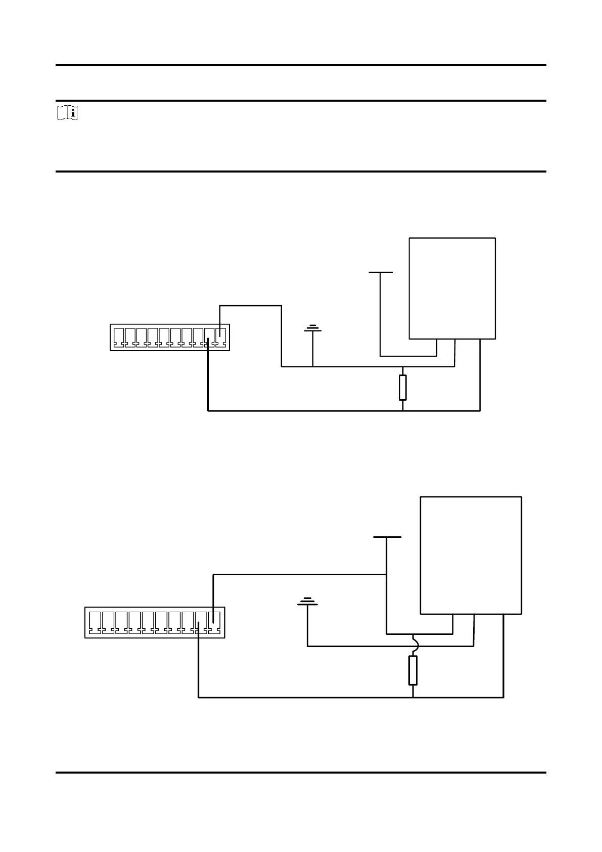
NPN Device
When connecting the GPIO interface of IO extended module to NPN device, it is recommended to
use 4.7 kΩ pull-up resistor.
NPN
Power Supply Ground
Signal Cable
R
VCC
Power Supply
DI
COM
COM
8 7 6 5 4 3 2 1
Figure 4-18 Connect to NPN Device

Questions and Answers:

Question and Answer IconNeed help?

Do you have a question about the HikRobot VC3000Pro Series and is the answer not in the manual?

HikRobot VC3000Pro Series Specifications

General IconGeneral
BrandHikRobot
ModelVC3000Pro Series
CategoryController
LanguageEnglish

Related product manuals