User Manual of DS-7200-SH/SV&DS-7300-SH Series DVR
18
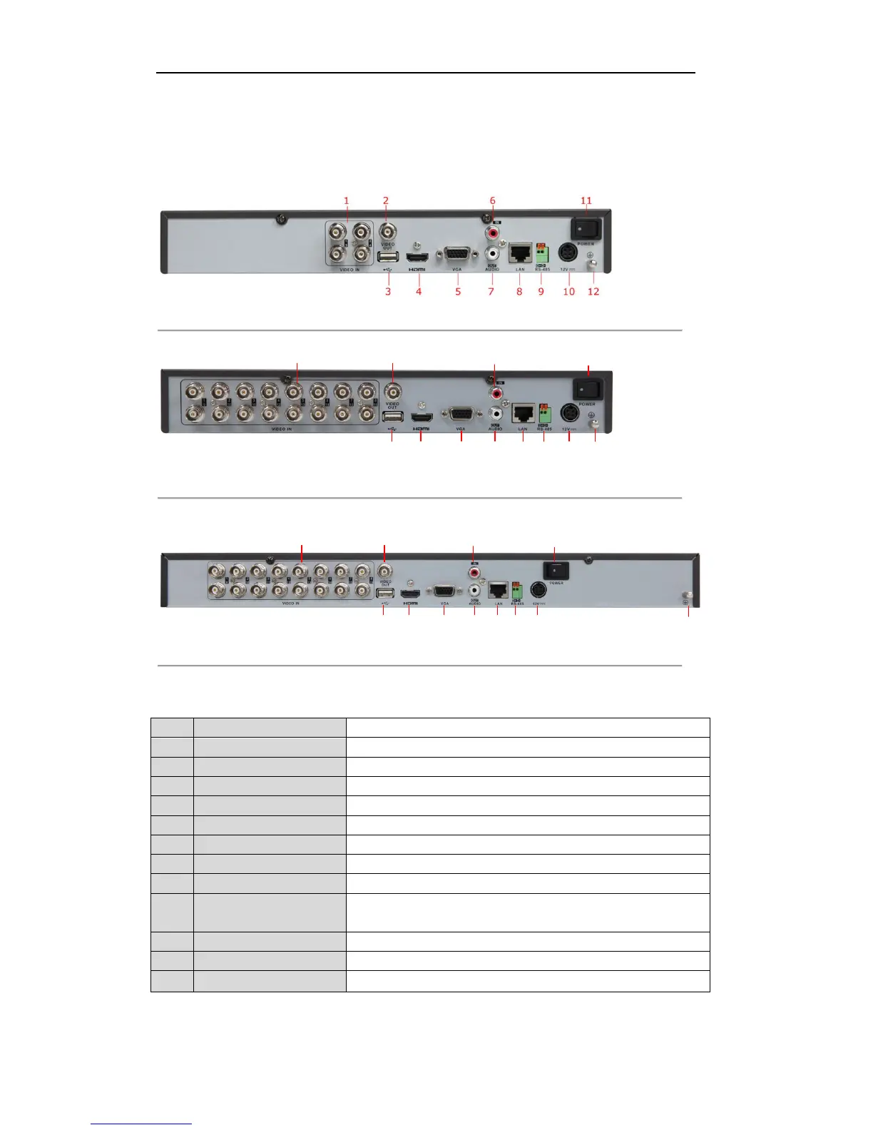
1.5 Rear Panel
The rear panels of DS-7200-SH/SV series DVR are shown in Figure 1.5, Figure 1.6 and Figure 1.7.
Figure 1.5 Rear Panel of DS-7204HVI/HFI/HWI-SH, DS-7204HVI-SV and DS-7204HWI-SV
Figure 1.6 Rear Panel of DS-7216HVI-SH and DS-7216HVI-SV
Note: The rear panel of DS-7208HVI-SH and DS-7208HVI-SV provides 8 video input interfaces.
Figure 1.7 Rear Panel of DS-7216HFI-SH and DS-7216HWI-SH
Note: The rear panel of DS-7208HFI-SH and DS-7208HWI-SH provides 8 video input interfaces.
Table 1.6 Description of Rear Panel
BNC connector for analog video input.
BNC connector for video output.
Connects USB mouse or USB flash memory devices.
DB15 connector for VGA output. Display local video output and menu.
RCA connector for audio input.
RCA connector for audio output.
Connector for LAN (Local Area Network).
Connector for RS-485 devices. Connect the D+ and D- terminals to T+
and T- of PTZ receiver respectively.
Switch for turning on/off the device.
Ground(needs to be connected when DVR starts up).
 Loading...