User Manual of Digital Video Recorder
25
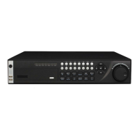
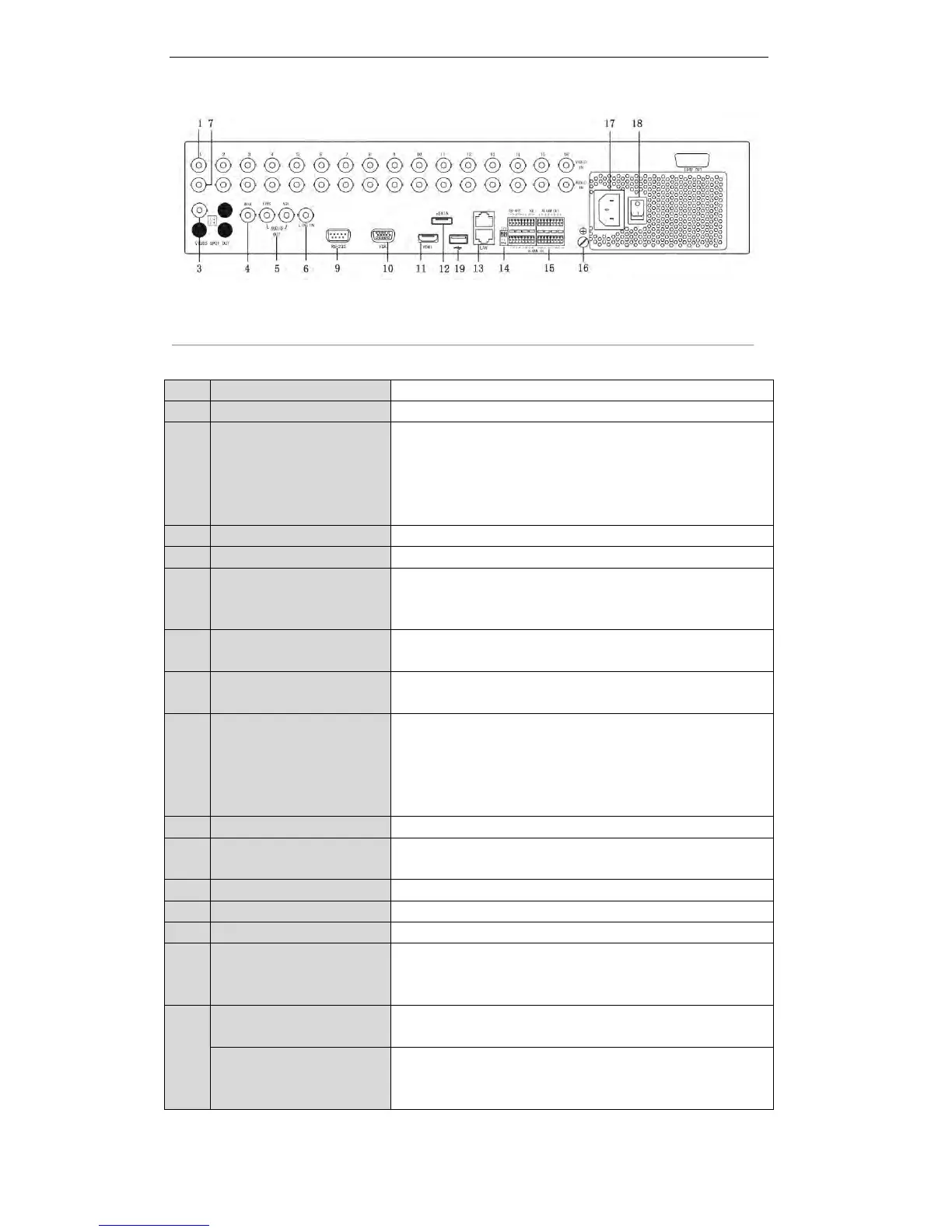
DS-8100/8000HWI-ST
Figure 1. 6 Rear Panel (1)
Table 1. 6 Description of Rear Panel (1)
BNC connector for analog video input.
LOOP OUT
(for
DS-9100/9000HFI-ST/RT/XT
& 9200/9100/9000HWI-ST
series)
BNC connector for video loop output.
BNC connector for video output.
BNC connector for video output.
RCA (for DS-9200/9100/9000 series) / BNC (for DS-8100/8000
series) connector for audio output. This connector is synchronized
with VIDEO OUT.
RCA (for DS-9200/9100/9000 series) / BNC (for DS-8100/8000
series) connector for two-way audio.
RCA (for DS-9200/9100/9000 series) / BNC (for DS-8100/8000
series) connector for audio input.
AUDIO IN
(for
DS-9100/9000HFI-ST/RT/XT
& 9200/9100/9000HWI-ST
series)
DB26 connector for audio input.
Connector for RS-232 devices.
DB9 connector for VGA output. Display local video output and
menu.
HDMI video output connector.
Connects external SATA HDD, DVD-R/W.
RS-485 termination switch.
Up position is not terminated.
Down position is terminated with 120Ω resistance.
Connector for RS-485 devices. T+ and T- pin connects to R+ and R-
pin of PTZ receiver respectively.
D+, D- pin connects to Ta, Tb pin of controller. For cascading
devices, the first DVR’s D+, D- pin should be connected with the
D+, D- pin of the next DVR.
 Loading...