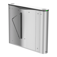
Figure 4-10 Remaining Closed
4.4.9 Exit Buon Wiring
The main and sub lane control board each has 1 buon interface,
which can be connected to exit buon or face recognion device.
Figure 4-11 Exit Buon Wiring
Note
●
The face recognion devices are powered via 12 VDC power
output interface of the main and sub lane control board.
●
Barrier open at the entrance: connect to BTN1 and GND.
●
Barrier open at the exit: connect to BTN2 and GND.
4.5 Device Sengs via Buon
You can congure the device via buon on the lane control board.
4.5.1
Conguraon via Buon
Buon Descripon
The buons are on the lane control board.
Figure 4-12
Buon
Exit Buon
●
Single press to open the gate from the entrance posion.
●
Double press to open the gate from the exit posion.
Parameter Conguraon Buon
●
LEFT: Press to add ten to conguraon data
●
RIGHT: Press to add one conguraon data
10
 Loading...