Page 28
EZCOM SETUP GUIDE
Configure the VFD’s parameters using the EZCOM parameter chart. Most of the parameters should already be
configured and only the ones highlighted in yellow should need to be changed.
Power down both VFD’s and connect the 2-wire shielded cable to the corresponding SN & SP terminals as shown in
the EZCOM circuit wiring example on the next page. Be sure to add the RS485 termination jumper to the B hoist VFD
as shown on the EZCOM circuit wiring example.
Add the tandem activation circuit to digital input 6 on each VFD as shown in the EZCOM circuit wiring example on the
next page.
Power up the VFD’s together at the same time and verify the communication is not disconnected by using the monitor
parameter db-08. If The value in db-08 = 9999
Operate the hoists in tandem and individually and verify correct operation.
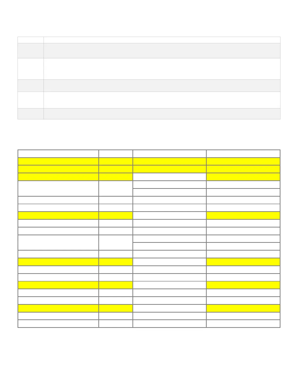
EZCOM PARAMETERS
Function Parameter Hoist A Hoist B
Digital Input 6 = Tandem Activation CA-06 95 95
EZCOM sync mode UE-43 1 = enabled speed + command 1 = enabled speed + command
EZCOM node ID CF-02 1 2
EZCOM communication error select CF-05
0 = trip with error 0 = trip with error
02 = prevent run / without error 02 = prevent run / without error
EZCOM communication time out CF-06 1.00 seconds 1.00 seconds
EZCOM communication wait time CF-07 2 ms 2 ms
EZCOM communication mode CF-08 03 = EZCOM Administrator 02 = EZCOM
EZCOM start node ID CF-20 1 1
EZCOM end node ID CF-21 2 2
EZCOM communication start method CF-22
00 = digital input 098:ECOM 00 = digital input 098:ECOM
01 = always start on power up 01 = always start on power up
EZCOM destination address 1
EZCOM destination register 1
EZCOM destination address 2
EZCOM destination register 2
EZCOM destination address 3
EZCOM destination register 3