Page 6
• Before inspecting the inverter,
be sure to turn off
the power supply and wait for more than 10 or 15
minutes depending on the invertor model
*1
(Before inspection, confirm that
the Charge lamp on
the inverter is off and the DC bus voltage between
terminals P and N is 45 V or less.)
• Before inspecting the inverter,
be sure to turn off
the power supply and wait for more than 10 or 15
minutes depending on the invertor model
*1
.
(Before inspection, confirm that the Charge lamp on
the inverter is off and the DC bus voltage between
terminals P and N is 45 V or less.)
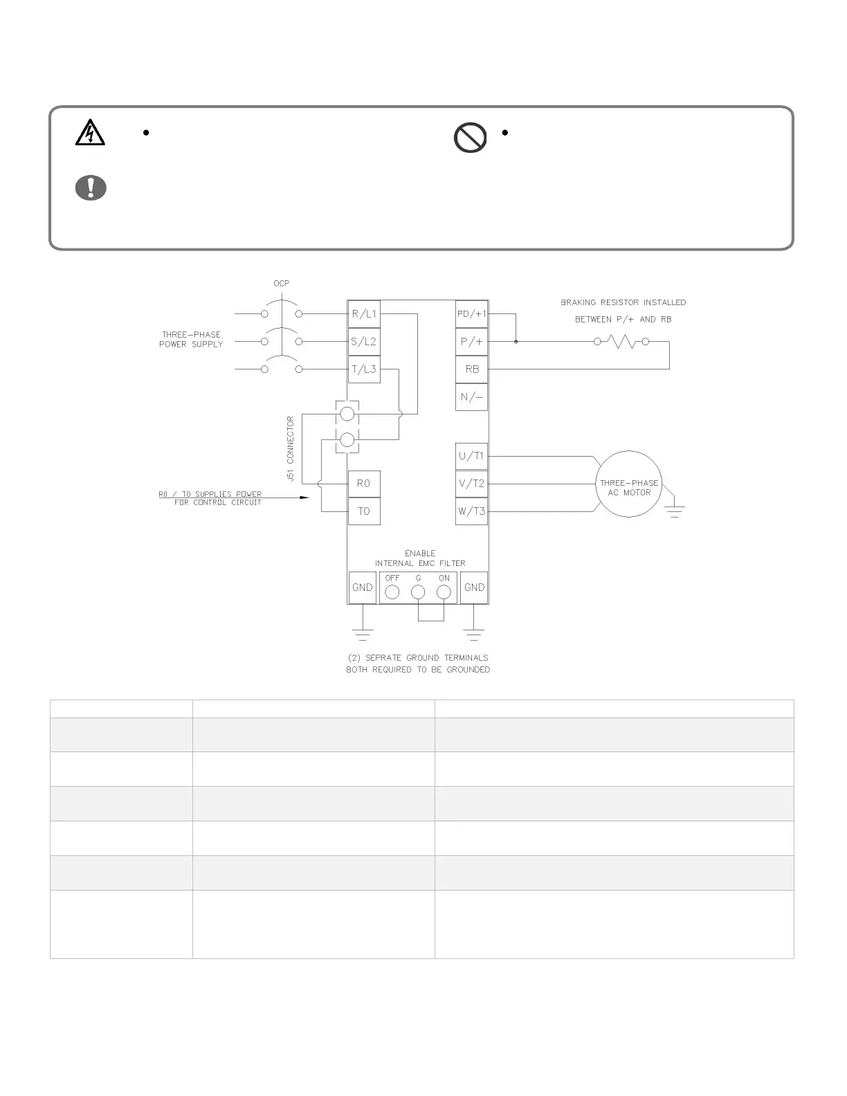
POWER CIRCUIT WIRING
Main power input (3-ph 50/60hz)
Connect to the AC power supply. Leave these terminals
unconnected when using a front end regenerative converter.
Inverter motor output Connect three-phase motor or load reactor.
DC link choke connection terminal
Remove the PD-P jumper from terminals, and connect the
optional DC link choke for power factor improvement.
DC bus positive and negative terminals.
Connection of a back end regenerative converter or external
braking unit.
Dynamic braking chopper circuit Connect braking resistor.
Control circuit power supply connection
Uses L1 & L3 for power for control circuit power supply. Can
also be reconfigured for to use DC bus by moving the J51
jumper and connecting R0 to terminal P/+ and T0 to terminal