Rev. 1.60 104 August 20, 2019 Rev. 1.60 105 August 20, 2019
BS66F340/BS66F350/BS66F360/BS66F370
Touch A/D Flash MCU with LED Driver
BS66F340/BS66F350/BS66F360/BS66F370
Touch A/D Flash MCU with LED Driver
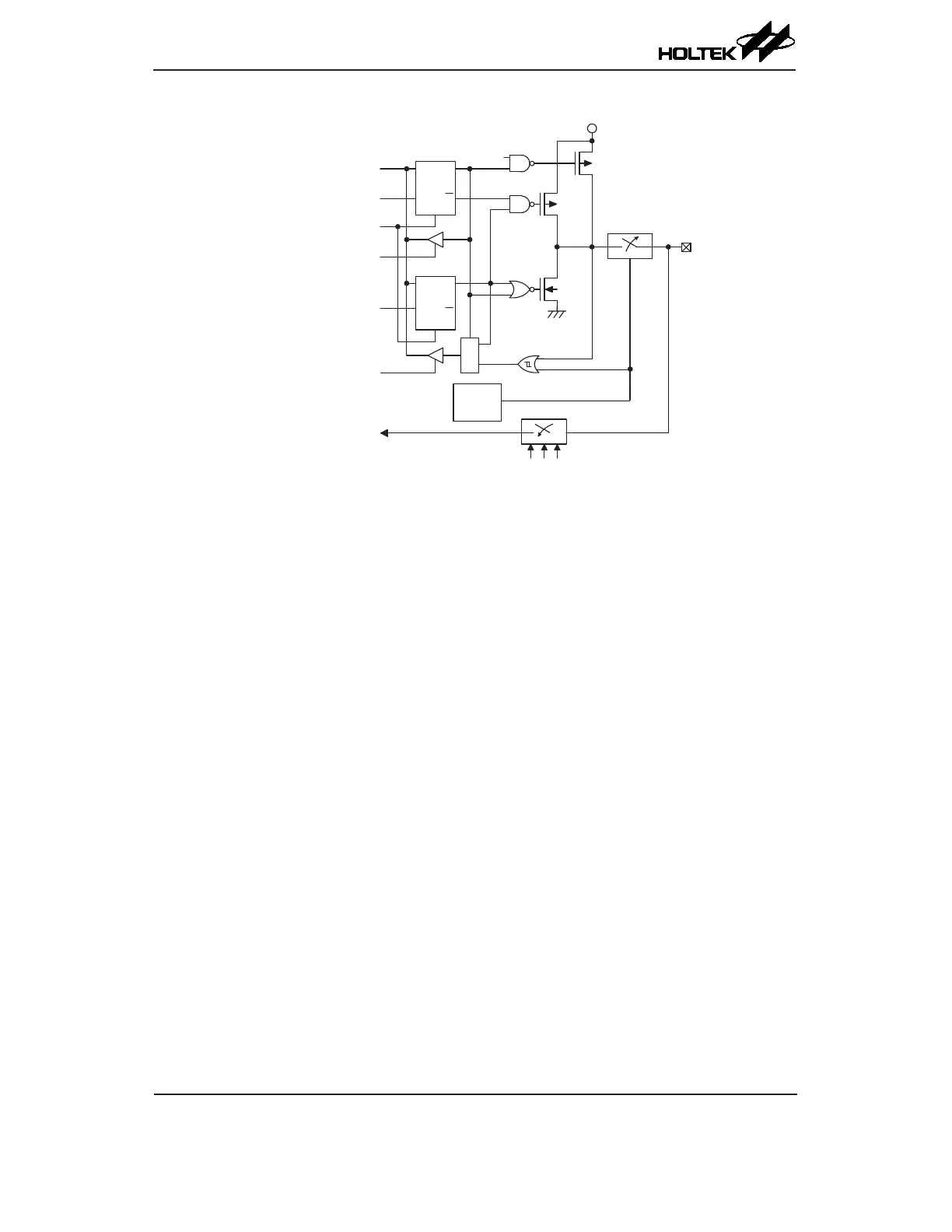
A/D Input/Output Structure
Programming Considerations
Within the user program, one of the things rst to consider is port initialisation. After a reset, all
of the I/O data and port control registers will be set to high. This means that all I/O pins will be
defaulted to an input state, the level of which depends on the other connected circuitry and whether
pull-high selections have been chosen. If the port control registers are then programmed to setup
some pins as outputs, these output pins will have an initial high output value unless the associated
port data registers are rst programmed. Selecting which pins are inputs and which are outputs can
be achieved byte-wide by loading the correct values into the appropriate port control register or
by programming individual bits in the port control register using the "SET [m].i" and "CLR [m].i"
instructions. Note that when using these bit control instructions, a read-modify-write operation takes
place. The microcontroller must rst read in the data on the entire port, modify it to the required new
bit values and then rewrite this data back to the output ports.
Port A has the additional capability of providing wake-up functions. When the device is in the
SLEEP or IDLE Mode, various methods are available to wake the device up. One of these is a high
to low transition of any of the Port A pins. Single or multiple pins on Port A can be setup to have this
function.