Rev. 1.60 84 August 20, 2019 Rev. 1.60 85 August 20, 2019
BS66F340/BS66F350/BS66F360/BS66F370
Touch A/D Flash MCU with LED Driver
BS66F340/BS66F350/BS66F360/BS66F370
Touch A/D Flash MCU with LED Driver
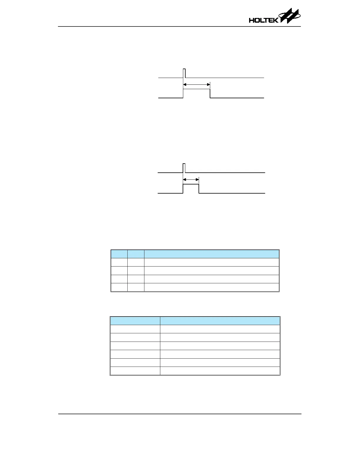
Watchdog Time-out Reset during Normal Operation
The Watchdog time-out Reset during normal operation is the same as the hardware Low Voltage
Reset except that the Watchdog time-out ag TO will be set to "1".
WDT Time-out
Internal Reset
t
RSTD
Note: t
RSTD
is power-on delay with typical time=16.7ms
WDT Time-out Reset during NORMAL Operation Timing Chart
Watchdog Time-out Reset during SLEEP or IDLE Mode
The Watchdog time-out Reset during SLEEP or IDLE Mode is a little different from other kinds
of reset. Most of the conditions remain unchanged except that the Program Counter and the Stack
Pointer will be cleared to "0" and the TO ag will be set to "1". Refer to the A.C. Characteristics for
t
SST
details.
WDT Time-out
Internal Reset
t
SST
WDT Time-out Reset during SLEEP or IDLE Mode Timing Chart
Reset Initial Conditions
The different types of reset described affect the reset ags in different ways. These ags, known
as PDF and TO are located in the status register and are controlled by various microcontroller
operations, such as the SLEEP or IDLE Mode function or Watchdog Timer. The reset flags are
shown in the table:
TO PDF Reset Function
0 0 Power-on reset
u u LVR reset during NORMAL or SLOW Mode operation
1 u WDT time-out reset during NORMAL or SLOW Mode operation
1 1 WDT time-out reset during IDLE or SLEEP Mode operation
"u" stands for unchanged
The following table indicates the way in which the various components of the microcontroller are
affected after a power-on reset occurs.
Item Reset Function
Program Counter Reset to zero
Interrupts All interrupts will be disabled
WDT, Time Base Clear after reset, WDT begins counting
Timer Modules Timer Modules will be turned off
Input/Output Ports I/O ports will be setup as inputs
Stack pointer Stack pointer will point to the top of the stack