Rev. 1.60 60 August 20, 2019 Rev. 1.60 61 August 20, 2019
BS66F340/BS66F350/BS66F360/BS66F370
Touch A/D Flash MCU with LED Driver
BS66F340/BS66F350/BS66F360/BS66F370
Touch A/D Flash MCU with LED Driver
Program Memory Bank Pointer – PBP
For the BS66F360 and BS66F370 device the Program Memory is divided into several banks.
Selecting the required Program Memory area is achieved using the Program Memory Bank Pointer,
PBP. The PBP register should be properly configured before the device executes the "Branch"
operation using the "JMP" or "CALL" instruction. After that a jump to a non-consecutive Program
Memory address which is located in a certain bank selected by the program memory bank pointer
bits will occur.
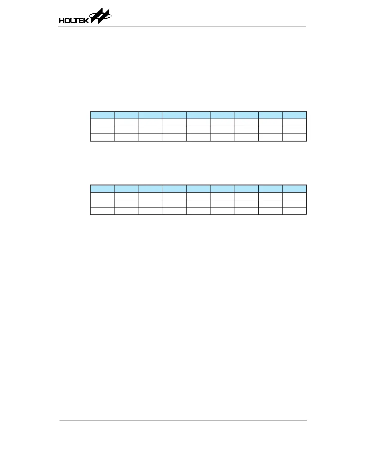
• PBP Register – BS66F360
Bit 7 6 5 4 3 2 1 0
Name D7 D6 D5 D4 D3 D2 D1 PBP0
R/W R/W R/W R/W R/W R/W R/W R/W R/W
POR 0 0 0 0 0 0 0 0
Bit 7~1 D7~D1: General data bits and can be read or written.
Bit 0 PBP0: Program Memory Bank Point bit 0
0: Bank 0
1: Bank 1
• PBP Register – BS66F370
Bit 7 6 5 4 3 2 1 0
Name D6 D5 D4 D3 D2 D1 PBP1 PBP0
R/W R/W R/W R/W R/W R/W R/W R/W R/W
POR 0 0 0 0 0 0 0 0
Bit 7~2 D6~D1: General data bits and can be read or written.
Bit 1~0 PBP1~PBP0: Program Memory Bank Point bit1~bit 0
00: Bank 0
01: Bank 1
10: Bank 2
11: Bank 3
Accumulator – ACC
The Accumulator is central to the operation of any microcontroller and is closely related with
operations carried out by the ALU. The Accumulator is the place where all intermediate results
from the ALU are stored. Without the Accumulator it would be necessary to write the result of
each calculation or logical operation such as addition, subtraction, shift, etc., to the Data Memory
resulting in higher programming and timing overheads. Data transfer operations usually involve
the temporary storage function of the Accumulator; for example, when transferring data between
one user defined register and another, it is necessary to do this by passing the data through the
Accumulator as no direct transfer between two registers is permitted.
Program Counter Low Register – PCL
To provide additional program control functions, the low byte of the Program Counter is made
accessible to programmers by locating it within the Special Purpose area of the Data Memory. By
manipulating this register, direct jumps to other program locations are easily implemented. Loading
a value directly into this PCL register will cause a jump to the specied Program Memory location,
however, as the register is only 8-bit wide, only jumps within the current Program Memory page are
permitted. When such operations are used, note that a dummy cycle will be inserted.