Rev. 1.60 208 August 20, 2019 Rev. 1.60 209 August 20, 2019
BS66F340/BS66F350/BS66F360/BS66F370
Touch A/D Flash MCU with LED Driver
BS66F340/BS66F350/BS66F360/BS66F370
Touch A/D Flash MCU with LED Driver
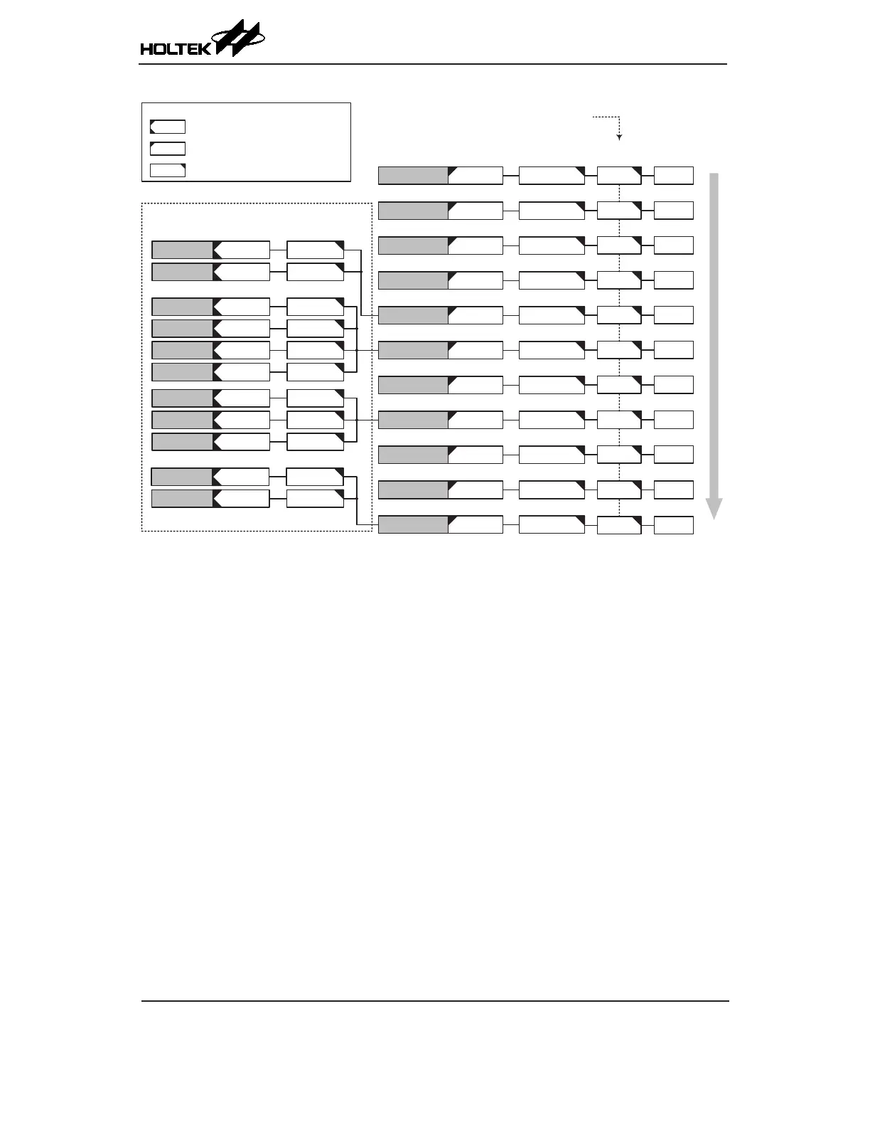
INT0 Pin
INT1 Pin
INT0F
INT1F
INT0E
INT1E
EMI 04H
EMI 08H
M. Funct. 0 MF0F MF0E
EMI 0CH
EMI 10H
EMI 14H
Time Base 0 TB0F TB0E
EMI 18H
LVD LVF LVE
EMI 1CH
Interrupt Name
Request
Flags
Enable Bits
Master
Enable
Vector
EMI auto disabled in ISR
High
Low
M. Funct. 1 MF1F MF1E
CTM0 P CTM0PF CTM0PE
CTM0 A CTM0AF CTM0AE
Interrupts contained within
Multi-Function Interrupts
xxE Enable Bits
xxF Request Flag, auto reset in ISR
Legend
xxF Request Flag, no auto reset in ISR
EMI 20H
A/D ADF ADE
EMI 24H
M. Funct. 2 MF2F MF2E
Time Base 1 TB1F TB1E
M. Funct. 3 MF3F MF3E
EEPROM DEF DEE
SIM SIMF SIME
UART URF URE
EMI 28H
CTM1 P CTM1PF CTM1PE
CTM1 A CTM1AF CTM1AE
EMI 2CH
Touch Key TKMF TKME
STM P STMPF STMPE
STM A STMAF STMAE
PTM P PTMPF PTMPE
PTM A PTMAF PTMAE
Interrupt Scheme
External Interrupt
The external interrupts are controlled by signal transitions on the pins INT0~INT1. An external
interrupt request will take place when the external interrupt request ags, INT0F~INT1F, are set,
which will occur when a transition, whose type is chosen by the edge select bits, appears on the
external interrupt pins. To allow the program to branch to its respective interrupt vector address,
the global interrupt enable bit, EMI, and respective external interrupt enable bit, INT0E~INT1E,
must first be set. Additionally the correct interrupt edge type must be selected using the INTEG
register to enable the external interrupt function and to choose the trigger edge type. As the external
interrupt pins are pin-shared with I/O pins, they can only be congured as external interrupt pins if
their external interrupt enable bit in the corresponding interrupt register has been set and the external
interrupt pin is selected by the corresponding pin-shared function selection bits. The pin must also
be setup as an input by setting the corresponding bit in the port control register. When the interrupt
is enabled, the stack is not full and the correct transition type appears on the external interrupt pin,
a subroutine call to the external interrupt vector, will take place. When the interrupt is serviced, the
external interrupt request ags, INT0F~INT1F, will be automatically reset and the EMI bit will be
automatically cleared to disable other interrupts. Note that any pull-high resistor selections on the
external interrupt pins will remain valid even if the pin is used as an external interrupt input.
The INTEG register is used to select the type of active edge that will trigger the external interrupt.
A choice of either rising or falling or both edge types can be chosen to trigger an external interrupt.
Note that the INTEG register can also be used to disable the external interrupt function.